You don’t need a chamber to make real progress on GNSS EMI mitigation. On one 700 mm quad we supported last quarter, RTK would drop to float the moment motors spooled. Median L1 C/N0 sat around 30–32 dB‑Hz and cycle slips spiked in hover. The root causes were typical: GNSS coax running parallel to battery and ESC phase leads, the antenna only 40 mm above a noisy top plate, and a 5.8 GHz VTX right beside the mast. A few hours of bench probing and a simple A/B flight plan lifted median C/N0 by ~4 dB‑Hz and kept RTK fixed throughout the same route. Here’s the exact playbook. Shielding and filtering assume a sound antenna to begin with—see our high-precision GNSS antenna selection guide if that choice is still open.
Prep: tools and quick safety checks
Before touching hardware, prep a minimal bench and a repeatable test route.
-
Spectrum analyzer (basic pre‑compliance is fine) with H‑field near‑field probes; optional E‑field probe for cable scans.
-
u‑blox (or equivalent) receiver with logging enabled; u-center 2 on a laptop for C/N0 histograms, fix timeline, and RAWX logging.
-
Optional: LISN (5 µH/50 Ω) for conducted emission checks on the power bus (CISPR 25 philosophy).
-
Insulated GNSS mast hardware, small copper/aluminum disc (60–90 mm) for a lightweight ground plane (if using patches).
-
Assorted ferrites/common‑mode chokes (SMD for RF, clamp‑ons for quick trials), feedthrough capacitors for DC penetrations, copper tape, conductive gasket material.
-
Torque driver for SMA/MCX, continuity meter for shield checks, strain‑relief parts.
Safety: power on a current‑limited bench supply when practical; prop‑off for bench tests. Document photos before you reroute anything so you can A/B precisely.
Key concepts that guide fixes
If you understand how noise couples, the fixes become obvious.
-
Coupling paths
-
Conducted on harnesses (power rails, grounds). Measured with a LISN per the CISPR 25 method using a 5 µH/50 Ω network—useful to see converter/ESC switching lines in 0.15–108 MHz. See Texas Instruments’ conducted test guidance in their application note and LISN explainer for context.
-
Radiated from loops/slots. Carbon‑fiber seams and cutouts can act like slot antennas if seams aren’t well bonded; treat those gaps. TE Connectivity’s UAV shielding notes emphasize continuous seams and gasketed joints to prevent leakage.
-
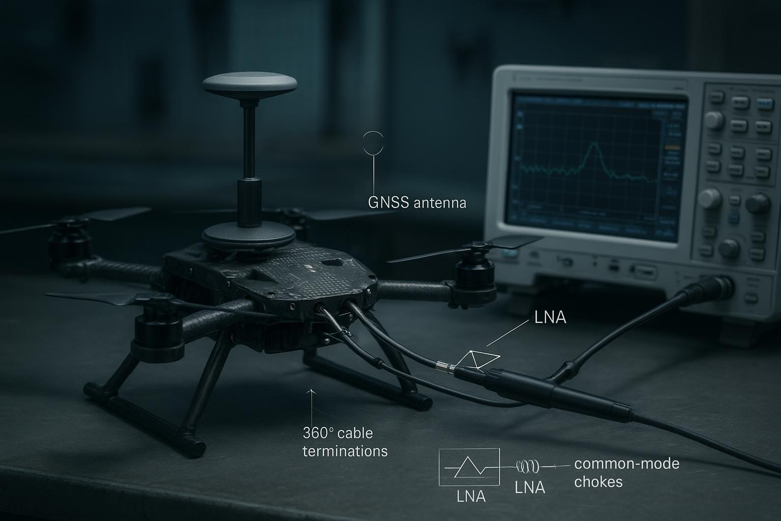
Common‑mode on shields. Coax shields and unshielded harnesses can carry RF as an antenna; stop it at entry/exit with common‑mode chokes and 360° terminations. Murata and Würth application notes recommend placing CM chokes right at the cable junction.
-
-
Antenna system basics on UAVs
-
Separation matters. PX4’s integration docs consistently recommend mounting GNSS high and away from motors/ESCs/radios, often on a mast. Numeric distances vary by platform—treat “more separation” as the right direction.
-
Ground plane vs. no ground plane. Patches prefer a stable ground plane (often ~70 × 70 mm class in vendor notes); helicals/quad‑helices tolerate minimal ground planes and offer uniform hemispherical patterns—useful on composite airframes.
-
Don’t fight the frame. Carbon fiber can detune antennas and change patterns; isolate the antenna on a non‑conductive mast and keep metal/composites away from the near field.
-
References you can show stakeholders:
-
PX4 mounting rationale: see GPS/compass mounting in the PX4 User Guide (“mount as far away from power lines and EMI as possible,” mast examples). Those pages are a good qualitative anchor: PX4 GPS/compass mounting guide
-
TE Connectivity’s system‑level shielding fundamentals (seams, gaskets, 360° cable bonds): TE Connectivity EMI shielding for drones
-
Murata’s CM choke placement basics: Murata common-mode choke basics
A step‑by‑step diagnostic workflow (bench → field)
- Bench near‑field pre‑scan
- With the H‑field probe, scan DC/DCs, ESCs, power rails, and the GNSS module while each subsystem is toggled on/off. Note peaks near GNSS L‑band and harmonics below 200 MHz that can mix up. Document probe locations and frequencies. Tektronix and Keysight have solid close‑field troubleshooting primers.
- Conducted power‑bus check (optional but helpful)
- Insert a 5 µH/50 Ω LISN on the main DC input and measure 0.15–108 MHz. This reveals converter/ESC spectral lines and confirms improvements after filters or rerouting. See TI’s conducted EMI note and LISN overviews for method details.
- Outdoor static baseline
- With props off and then on (idle), log 10–15 minutes of sky‑view static. In u‑center 2, record: C/N0 histograms per constellation, fix timeline, and RAWX for slip flags. Keep elevation mask conservative (e.g., 10–15°) so you can see sensitivity effects.
- A/B flight route
- Define a short repeatable route with stable sky view. Fly A (baseline), implement one change, fly B. Keep weather and time similar. Track: median C/N0 (per band), time‑in‑fix, and slip counts. Repeat per change; avoid stacking three fixes before testing or you won’t know what helped.
Authoritative anchors for stakeholders:
-
CISPR 25 LISN context: TI CISPR 25 conducted-EMI note and a LISN explainer: CISPR 25 LISN edition-4 requirements
-
C/N0 and slips as quality indicators: Kubo et al. discuss how C/N0 fluctuations relate to tracking robustness: https://pmc.ncbi.nlm.nih.gov/articles/PMC7411688/
Practical GNSS EMI mitigation recipes (layered, start cheap)
Start with routing and bonding, then add filtering, then revisit shielding.
-
Cable routing and geometry (Easy)
- Keep GNSS coax and sensor leads away from battery and ESC phase wires; avoid long parallel runs. When unavoidable, cross power at 90°. Add strain relief so the shield termination doesn’t loosen over time. PX4’s GNSS mounting guidance supports “distance first” design.
-
Common‑mode control at entry/exit (Easy → Moderate)
-
Add a common‑mode choke at the antenna feed or immediately at the receiver RF connector. Place it as close as practical (millimeters) to the connector. Murata/Würth app notes stress proximity for best CM suppression.
-
On DC lines into the GNSS module, use feedthrough capacitors at bulkhead/board entry.
-
-
Mast and ground plane optimization (Easy → Moderate)
-
Raise the antenna. For medium multirotors, 80–120 mm masts are common practice; use non‑conductive standoffs to avoid coupling to the frame. If you use a patch, add a thin 60–90 mm copper/aluminum disc as a local ground plane; verify no detuning near CF.
-
When ground plane is constrained, consider a helical/quad‑helix style antenna with built‑in LNA and filtering.
-
-
Shield seams and 360° terminations (Moderate)
- Enclose noisy subsystems (VTX, DC/DC bays) and treat seams with conductive gaskets; ensure continuous 360° shield terminations at bulkheads/connectors. TE Connectivity’s UAV notes cover materials and seam design.
-
Filtering architecture (Moderate → Advanced)
-
Pre‑LNA SAW/BPF can protect against strong out‑of‑band blockers but raises noise figure roughly by its insertion loss (Friis). Typical SAW IL ~1.1–1.5 dB; add only when needed and verify C/N0 impact. Fuji Crystal’s practical guide explains the IL ↔ NF trade.
-
Keep the first LNA as close to the antenna as feasible; consider post‑LNA filters when blocking is manageable upstream. Qorvo’s filter notes and SAW product pages are good references.
-
Example effort vs. impact (indicative, not guarantees):
Mitigation | Effort | Typical effect on median C/N0 |
|---|---|---|
Reroute coax away from power, 90° crosses | Low | +2–3 dB‑Hz |
Add CM choke at RF feed + feedthrough on DC | Low–Med | +1–3 dB‑Hz |
80–120 mm mast + 60–90 mm ground plane | Med | +2–4 dB‑Hz |
Shield seams + 360° terminations | Med–High | +1–3 dB‑Hz |
Pre‑LNA SAW (only if blockers) | Med | −1 to −1.5 dB NF, but improved blocking; net C/N0 varies |
References for this section:
-
TE shielding fundamentals for seams and terminations: TE Connectivity EMI shielding for drones
-
SAW/NF trade‑offs: How to choose an optimal SAW filter and Qorvo filter notes: Qorvo RF filter technology facts
-
PX4 GNSS mounting guidance: PX4 GPS/compass mounting guide
Validation cookbook: what to log and how to decide “done”
-
u‑center logging
-
Enable NAV‑PVT for fix state and accuracy; enable RXM‑RAWX for per‑satellite C/N0 and slip flags; record 10–15 minutes static and per‑flight logs. u‑center 2 user guide explains logging workflows and message capture.
-
Track: median and 10th‑percentile C/N0 per band, time‑in‑fix (float vs fixed), and slip counts during hover.
-
-
Bench spectra
- Save “hot‑spot” spectra near ESCs, DC/DCs, and at the GNSS RF input before/after mitigations. Label probe position and subsystem state in the screenshot filename.
-
Pass/fail heuristics (example targets, not promises)
-
Median L1 C/N0 uplift ≥ +3 dB‑Hz after routing+CMC+mast.
-
Slip count in 2‑minute hover reduced by 50% or more.
-
Time‑in‑RTK‑fixed improves to near‑continuous on the same route.
-
Helpful references:
-
u‑blox interface docs (RAWX/measurements): interface description documents UBX-20053845 and UBX-20046191
-
C/N0 quality context and slips: https://pmc.ncbi.nlm.nih.gov/articles/PMC7411688/
Productionization: make the fix stick in manufacturing
-
Harness drawings
- Encode keep‑outs from power rails, 90° cross rules, and explicit locations for CMCs/feedthroughs. Call out 360° shield bonds and torque specs for RF connectors.
-
Receiving inspection & QC
- Verify shield continuity, gasket compression, and strain relief. Use a short checklist at incoming QC to catch missing shield bonds.
-
Regression scripts
- Keep a bench pre‑scan map and a fixed outdoor static + flight route. Store “golden” C/N0 histograms and spectra, and compare each production change to those baselines.
Stakeholder context:
- You don’t need to certify to DO‑160, MIL‑STD‑461, or CISPR 25 to benefit from their philosophies. Point managers to these overviews if they want a framework: DO‑160 summary: DO‑160 environmental testing overview ; MIL‑STD‑461 overview: MIL‑STD‑461 EMC testing overview
Practical example: 700 mm quad A/B (what actually moved the needle)
Baseline configuration
-
GNSS patch antenna 40 mm above the top plate; VTX within 60 mm; GNSS coax running parallel to battery and ESC phase leads for ~180 mm.
-
Bench: near‑field scan showed strong H‑field near ESC bay at 40–70 MHz and harmonics; weaker but broad noise at the GNSS RF input when motors spooled.
-
Field: median L1 C/N0 ≈ 31 dB‑Hz; frequent slips; RTK fixed → float transitions during hover.
Mitigations applied (one at a time, with flights between)
-
Rerouted GNSS coax to avoid parallel run; forced 90° crosses where needed.
-
Added a small common‑mode choke at the antenna feed and feedthrough capacitors at the GNSS module DC entry.
-
Raised the antenna on a 120 mm non‑conductive mast with an 80 mm aluminum disc as a local ground plane (verified no detuning vs CF).
-
Sealed VTX bay seam with conductive gasket and improved 360° braid termination at bulkhead.
Observed outcomes (same time of day, similar sky view)
- Median L1 C/N0 improved by ~4 dB‑Hz (to ~35 dB‑Hz). Cycle slips during a 2‑minute hover dropped by ~60%. RTK remained fixed on the comparison route. These are example results, not universal guarantees—your platform will vary.
Where a better antenna helps
- On tight frames where separation and ground plane are constrained, a high‑rejection, stable‑phase GNSS antenna can reduce the burden on filtering and placement. For example, some teams source such antennas from GNSource when they can’t lift the antenna much higher or expand a ground plane. Keep evaluation neutral: verify with your own C/N0 and fix‑stability logs.
Key takeaways
-
GNSS EMI mitigation is a layered job: source control → routing/bonding → filtering → verification. Start cheap, test, and only add complexity when logs demand it.
-
Separation and common‑mode control deliver fast wins. A mast (80–120 mm) plus a CMC at the RF feed often adds multiple dB‑Hz to median C/N0.
-
Pre‑LNA SAW filters protect against blockers but cost noise figure. Measure the C/N0 trade before making them permanent.
-
Treat carbon‑fiber seams and cable entries like antennas. Use conductive gaskets and 360° terminations to close leakage paths.
-
Validate with data, not vibes: C/N0 histograms, slip counts, and repeatable A/B flights decide what stays.
Short FAQ
-
How close is “too close” for GNSS to ESCs and power rails? There’s no single number across airframes. Follow the principle in PX4’s guidance—maximize separation and avoid parallel runs. In practice on medium quads, lifting the antenna by 80–120 mm and rerouting coax away from power typically helps.
-
Do I need a chamber to do GNSS EMI mitigation? No. Near‑field probing, a simple LISN check, outdoor static, and a repeatable flight route get you 90% of the way.
-
Should I always add a SAW filter before the LNA? No. A pre‑LNA SAW adds ~1–1.5 dB insertion loss and degrades NF correspondingly. Use it when strong blockers exist and you’ve verified net tracking improvement in your logs.
-
Patch or helix for drones? If you can afford a decent ground plane and height, a patch is efficient and stable. On tight, composite frames with little ground plane, helicals often hold pattern and consistency better.
-
What’s the fastest first change when RTK is flaky at takeoff? Reroute the GNSS coax away from power, add a CM choke at the RF feed, and lift the antenna. Then re‑fly and check C/N0 and slips before doing more.
References and further reading (selected)
-
PX4 GNSS/compass mounting and assembly pages: PX4 GPS/compass mounting ; PX4 multicopter assembly ; PX4 GPS & compass hardware
-
TE Connectivity — EMI shielding for drones: TE Connectivity EMI shielding for drones
-
Murata CM choke placement basics: Murata common-mode choke basics
-
SAW/NF trade‑offs: How to choose an optimal SAW filter ; Qorvo filter notes: Qorvo RF filter technology facts
-
CISPR 25 LISN context (TI note + explainer): TI CISPR 25 conducted-EMI note ; CISPR 25 LISN edition-4 requirements
-
C/N0 quality and slip connections (research context): https://pmc.ncbi.nlm.nih.gov/articles/PMC7411688/

![How to Set Up an RTK Base Station Antenna [2026 Guide]](/blog/_assets/upload/aaacdd5rjxygrxhc/2026/06/17/image_1781704508-i4v1t4p5.jpeg)