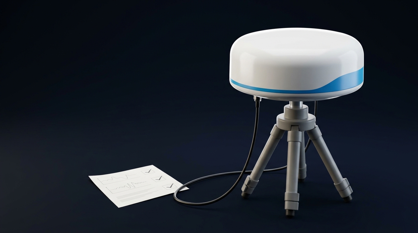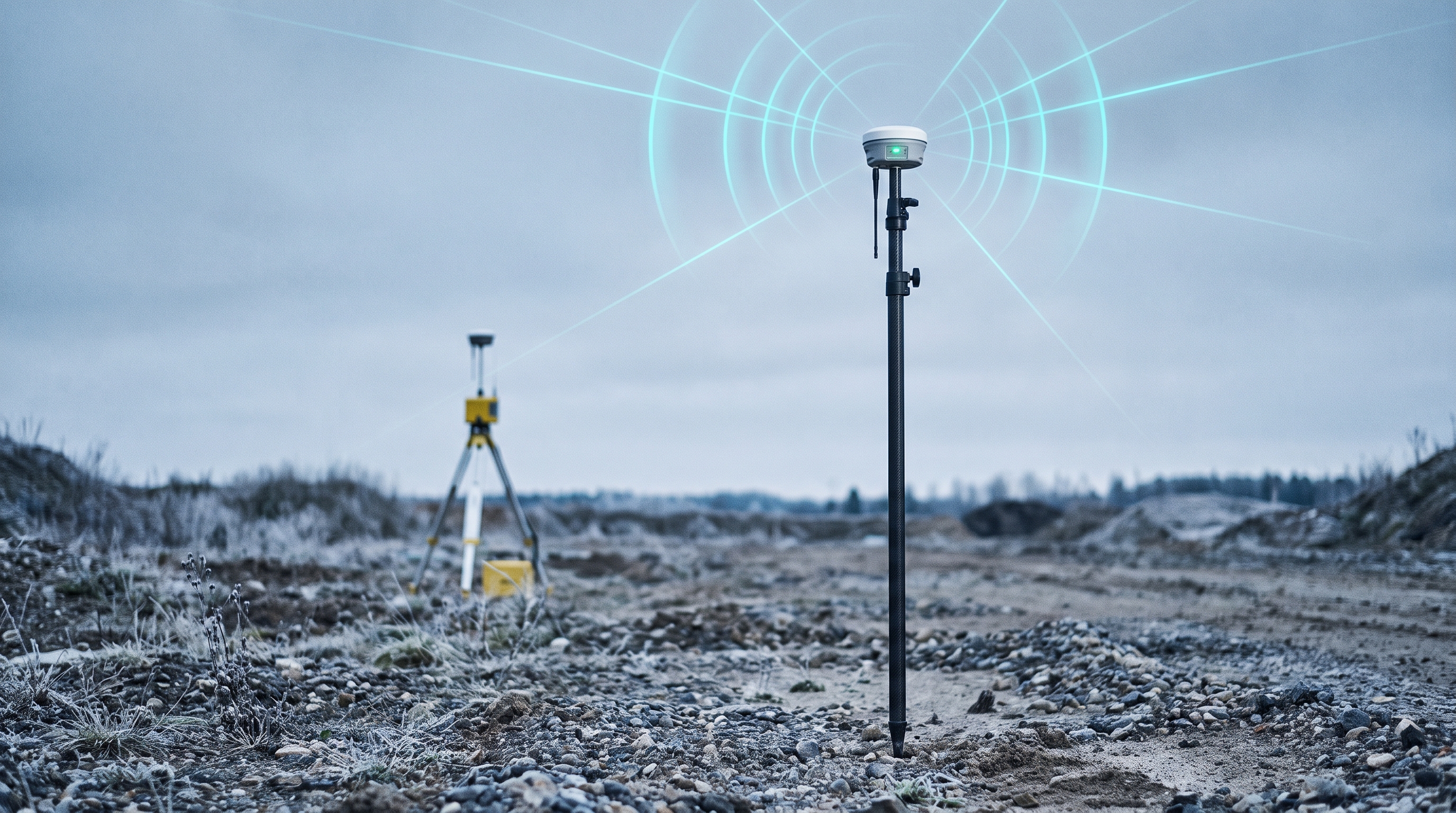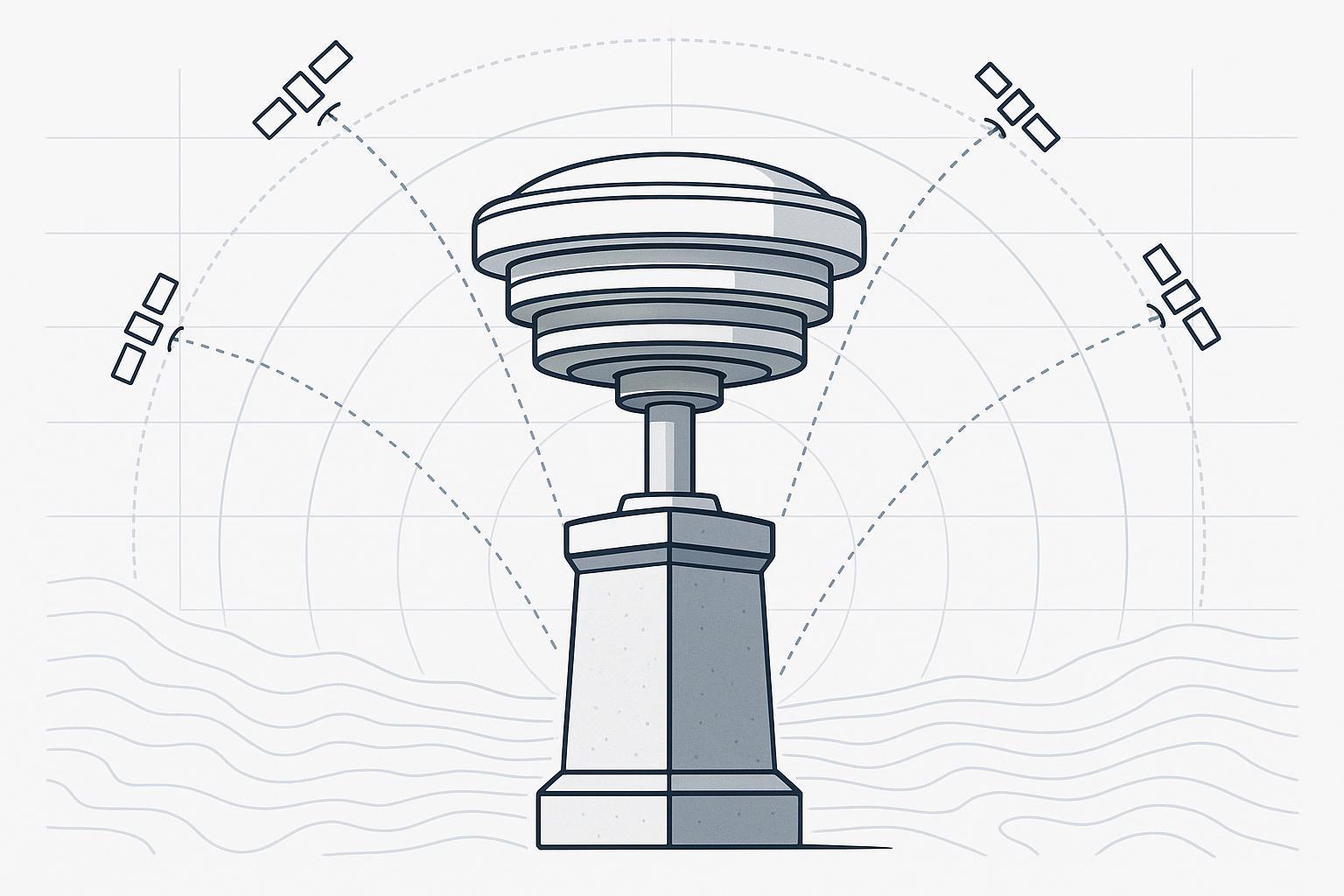
If you’ve ever seen RTK fixes that look stable one minute and drift the next—or a CORS time series that slowly “breathes” in height—there’s a good chance the root cause is not your math. It’s RF reality.
A GNSS antenna is where precision starts. It shapes what your receiver can measure and what it has to guess its way through. In surveying, RTK, and CORS (continuously operating reference station) work, that often means the difference between repeatable centimeter performance and days of re-observations.
This guide explains what “high precision” actually means for GNSS antennas, how to evaluate the specs that matter (and ignore the ones that don’t), and how to install and document antennas so your results remain defensible. For a step-by-step selection walkthrough, our buyer’s guide to high-precision GNSS antennas pairs well with the specs covered here.
How to choose a high-precision GNSS antenna for the field
Antenna datasheets can feel like an ocean of numbers. For high-precision GNSS, only a few categories reliably correlate with better survey outcomes.
1) Phase center behavior (PCO/PCV)
GNSS measurements are referenced to an antenna’s phase center—an electrical point that usually isn’t the geometric center and doesn’t stay perfectly fixed across directions and frequencies.
-
Phase Center Offset (PCO): the average offset between the antenna reference point (ARP) and the electrical phase center.
-
Phase Center Variation (PCV): how that phase center shifts with satellite elevation/azimuth and signal frequency.
The ESA explains that phase center is direction-dependent and frequency-dependent—exactly why PCV exists in the first place (see ESA Navipedia on “Antenna Phase Centre”).
In practical terms: if your antenna’s phase center moves around as satellites rise and set, you’ll see it most painfully in height and in repeatability between sessions.
2) Multipath rejection
Multipath is the silent killer of precision GNSS. A receiver doesn’t just see the direct satellite signal; it can also see delayed reflections off the ground, vehicles, water, building faces, rails, and even nearby antenna mounts.
Some antenna designs (and installation practices) reduce how much reflected energy makes it into the correlation process. But no antenna can “fix” a poor site.
In other words, “GNSS antenna multipath mitigation” is always a system property: antenna architecture + mount + nearby reflectors + how you observe.
⚠️ Warning: If you install a great antenna in a bad multipath environment, you usually get “great multipath”—clean-looking data that’s consistently biased.
3) Polarization quality (axial ratio)
GNSS satellites transmit right-hand circularly polarized (RHCP) signals. Reflections often flip polarization, so antennas with better polarization purity (often expressed via axial ratio) tend to be more selective against unwanted reflections.
4) Stable gain pattern at low elevations
Survey-grade work often benefits from tracking low-elevation satellites for geometry—but low elevation is also where multipath risk is highest.
A “high precision” antenna typically has a gain pattern and front-end design that’s stable and well-characterized across the elevation angles you actually use.
5) Filtering and interference resilience
Even when you’re not in a jamming scenario, real sites can be noisy. Cellular, telemetry, nearby radios, and on-site electronics can raise the noise floor.
Front-end filtering and linearity matter, but they’re hard to judge from a single number. When in doubt, ask for the vendor’s interference and out-of-band rejection characterization.
GNSS antenna phase center basics: PCO/PCV and calibration models
There are two “reference points” you’ll hear about:
-
ARP (Antenna Reference Point): a physical point defined on the antenna, used for measuring antenna height.
-
Phase center: the electrical origin the GNSS measurement is referenced to.
Your goal isn’t to pretend these are the same. Your goal is to connect them correctly using calibration information.
The NOAA National Geodetic Survey explains how calibration approaches work in the NGS ANTCAL FAQ, including the difference between relative and absolute calibrations and how PCV is represented.
What to ask for (especially for CORS and high-precision base stations)
When you care about repeatability and published coordinates, ask the antenna supplier for:
-
An absolute calibration model (commonly distributed via ANTEX files in geodetic workflows)
-
Calibration details for any radome or protective enclosure, if used
-
Clear documentation of the ARP definition and measurement method
This isn’t paperwork theater—PCV corrections are how you keep millimeter-level behavior from turning into centimeter-level height errors over time.
Multipath: what it is, how it shows up, and what you can do about it
Multipath is a propagation problem: your antenna receives a mixture of the direct signal and one or more delayed reflections. If the reflections are strong enough, they distort the observed carrier phase and code measurements.
What multipath looks like in real survey work
You might see:
-
RTK solutions that repeatedly “fix” but don’t repeat at the same point
-
Height residuals that look periodic (daily patterns are common at static stations)
-
Increased cycle slips or longer ambiguity resolution times near reflective surfaces
How antenna design helps (and where it doesn’t)
Antenna choices can reduce multipath sensitivity—especially from low elevation angles—but installation dominates.
As a rule of thumb:
-
Choke ring / advanced ground-plane designs are preferred for permanent stations and high-stability work.
-
Compact rover antennas trade multipath performance for size and handling.
The key is matching the antenna and the site to the level of precision you’re claiming.
GNSS antenna form factors: patch, helical, choke ring, multi-feed
Different antenna architectures are built for different constraints.
According to VectorNav’s overview of GNSS RF hardware, common GNSS antenna types include patch, helical, and choke-ring designs (see VectorNav’s GNSS antenna primer).
Here’s how to think about them for surveying, RTK, and CORS.
Patch antennas
-
Pros: low profile, low cost, easy integration.
-
Cons: typically less robust phase center behavior and weaker multipath rejection than survey-grade designs.
Use patches when SWaP dominates and the measurement problem doesn’t demand maximum stability.
Helical antennas
-
Pros: strong circular polarization performance; good for rejecting off-angle signals.
-
Cons: form factor can be taller; performance varies widely by design.
Choke ring antennas
-
Pros: top-tier multipath mitigation and phase center stability; standard choice for reference stations.
-
Cons: larger, heavier, more expensive.
If you’re building a true reference station or doing deformation monitoring, choke ring designs are usually where you end up.
Multi-feed antennas
-
Pros: can improve polarization performance and pattern stability compared to single-feed designs.
-
Cons: requires careful design; still not magic if the site is reflective.
RTK base vs rover: how requirements diverge
High-precision workflows often fail because the base and rover are treated as “two of the same thing.” They aren’t.
RTK base antenna: prioritize stability and traceability
For a base (especially if it supports many projects over time), prioritize:
-
Stable phase center behavior (PCO/PCV)
-
Multipath mitigation (design + site)
-
Clear ARP documentation and repeatable mounting
-
Environmental stability (thermal, mechanical)
Rover antenna: prioritize usability without pretending it’s a CORS antenna
For a rover, prioritize:
-
Consistent handling and centering
-
Ruggedness and repeatable pole setup
-
Sufficient multi-frequency support for fast ambiguity resolution
In practice, rover results often improve more from better field discipline (site selection, pole handling, observation time) than from chasing tiny spec deltas.
CORS and permanent reference stations: what changes
CORS is where “good enough” becomes expensive.
A permanent station is judged by what it produces over months and years, not what it produces on one nice day.
Radomes: helpful for weather, risky for heights
The NOAA NGS explicitly notes in its CORS Guidelines that antenna radomes can change the antenna phase center and are generally discouraged for CORS installations.
If you do use a protective enclosure, treat the antenna + radome as a paired system and confirm calibration support.
Change control matters
Even small changes can corrupt a time series:
-
Antenna swaps
-
Mount modifications
-
Cable reroutes
-
Nearby construction introducing reflections
Long-lived stations need a simple rule: if you change anything that could affect RF or geometry, document it and expect to re-validate.
Multi-frequency and multi-constellation: why it’s now the default
Modern surveying receivers commonly track multiple constellations and multiple frequencies.
Multi-frequency matters because ionospheric delay depends on frequency; combining measurements across frequencies is one of the most effective ways to mitigate ionospheric error.
NovAtel summarizes why multi-frequency and multi-constellation tracking improves robustness and error mitigation in its primer on multi-frequency GNSS error reduction.
In the antenna context, this means you should confirm:
-
The antenna truly supports the bands your receiver uses for precision
-
Gain and group delay characteristics are acceptable across those bands
-
Calibration models exist for the antenna configuration you’ll deploy
Installation checklist: the fastest way to lose centimeters
A high-precision antenna can’t compensate for a sloppy setup. Use this as a pre-flight checklist.
Site selection
-
Choose open sky with minimal reflective surfaces in the near field.
-
Avoid nearby metal structures, walls, and vehicle traffic patterns.
-
Watch the horizon: low-elevation tracking is where reflections tend to dominate.
Mounting and centering
-
Use a rigid, repeatable mount.
-
Ensure the antenna is level per manufacturer guidance.
-
For pole work, build a habit of redundant checks (bubble, bipod discipline, consistent rod height measurement).
Cabling and power
-
Use quality cable and protect connectors from water ingress.
-
Strain-relieve the cable so wind doesn’t translate into motion at the antenna.
Documentation you’ll thank yourself for later
-
Antenna make/model, serial number
-
Firmware/receiver configuration that affects tracking
-
Measured antenna height to ARP and method
-
Any radome/enclosure information
-
Photos of the installation and surrounding environment
Pro Tip: For permanent stations, treat “documentation” as part of the antenna system. You can’t troubleshoot what you didn’t record.
How to validate performance before you trust it
You don’t need a lab to catch the most common mistakes.
-
Run repeat observations at different times of day.
-
Compare height stability, not just horizontal.
-
Change only one variable at a time when troubleshooting (site, mount, cable, antenna).
-
For reference-style work, consider publishing or checking solutions with established workflows and guidance (NOAA NGS provides extensive documentation and tooling around CORS and related processing; start with the NGS CORS overview).
Next steps
If you’re selecting antennas for surveying, RTK, or a reference station build, start by writing down your constraints:
-
Bands/constellations required by your receiver
-
Base vs rover vs permanent station role
-
Expected multipath environment
-
Whether you need calibration models for publishable coordinates
-
Mechanical mounting and environmental exposure
From there, browse categories and narrow by architecture and documentation maturity. GNSource maintains a product hub at GNSource GNSS antenna products and a dedicated category for GNSource high-precision measurement antennas.