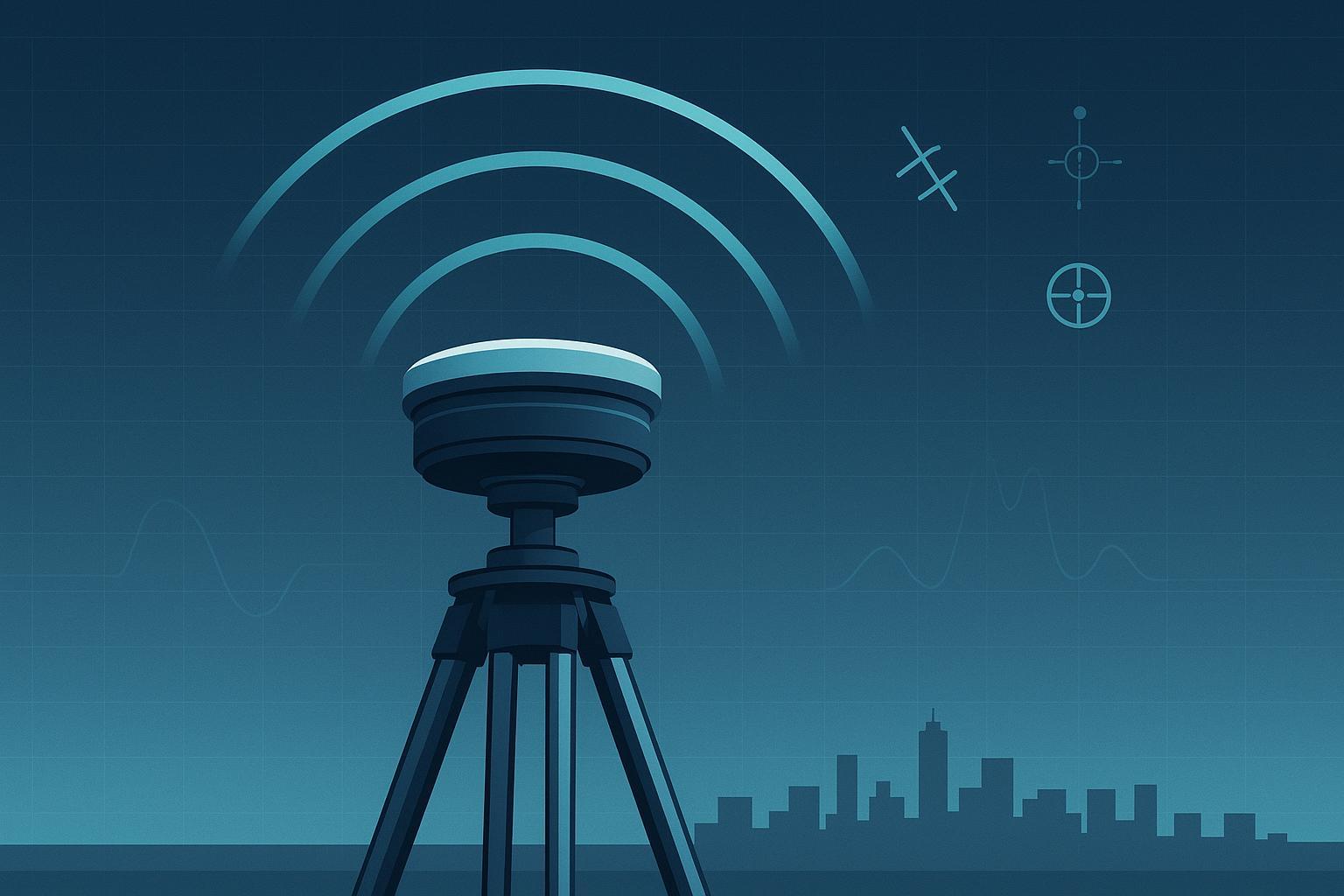
On a façade‑inspection job last spring, our multirotor lost RTK lock three times skimming past mirrored glass and stainless HVAC boxes. CN0 dipped, cycle slips spiked, and the fix ratio cratered just as the pilot needed centimeter‑level hold. Fifty meters away, a survey crew’s permanent base purred along with a choke ring antenna on a rigid mast, oblivious to the rooftop reflections. That contrast captures the heart of this guide: what a choke ring GNSS antenna actually does, why it’s fantastic for reference stations, and why most UAVs shouldn’t carry one. It’s one slice of the broader decision our high-precision GNSS antenna buyer’s guide walks through end to end.
What a choke ring GNSS antenna actually does
A choke ring GNSS antenna places a precision radiating element in the center of concentric quarter‑wavelength “chokes.” Those grooves behave like a high‑impedance boundary, damping surface waves on the ground plane and attenuating energy creeping in from low elevation angles. In plain language: it lets direct, right‑hand circularly polarized signals from the open sky in while strongly discouraging shallow, reflected paths that cause multipath.
Industry references describe this class of “multipath‑limiting” antennas and their low‑elevation suppression role. The u‑blox GNSS Antennas application note outlines choke‑ring principles among other designs, emphasizing how geometry shapes rejection of near‑horizon reflections. See the overview in the u‑blox guide under multipath‑limiting antennas in the GNSS Antennas application note (UBX‑15030289).pdf). Engineering texts also point to surface‑wave attenuation achieved by these choke structures; the U.S. Army Corps of Engineers summarizes choke‑ring behavior and pattern shaping in its EM 1110‑2‑1009 manual (2018).
Why are choke rings common on permanent stations? Because they reduce site‑dependent errors, especially ground‑reflected multipath that changes slowly with the environment. UNAVCO’s knowledge base notes that carefully chosen antennas and ground planes mitigate near‑ and far‑field multipath at geodetic sites; see UNAVCO’s site‑dependent error guidance for context.
Implications for UAV RTK reliability
Here’s the deal: a choke ring’s superpower is stability—especially of the phase center at low elevations. That’s gold for a static or semi‑static base, but a moving airframe brings added variables.
-
Phase Center Offset (PCO) and Phase Center Variation (PCV): PCO is the fixed vector from the antenna reference point (ARP) to the average electrical phase center; PCV is how that phase center shifts with elevation/azimuth and frequency. The NGS ANTCAL FAQ defines both and explains why per‑frequency calibration matters. If you ignore PCO/PCV, you bake in centimeter‑level biases—bad news for ambiguity resolution.
-
ANTEX files: Processing engines use ANTEX to load frequency‑specific PCO/PCV for antennas/satellites. The IGS primer on applying antenna phase center corrections gives a practitioner‑friendly treatment in IGS antenna phase center corrections (GPS World).
-
Dynamic platforms: A UAV is subject to attitude changes, rotor wash, and airframe‑induced shading. Even if the antenna is calibrated on a ground fixture, the instantaneous incident angle distribution in flight differs, so the effective PCV you experience is a mix of the lab calibration and the platform’s dynamics.
-
Elevation masks: A practical way to reduce low‑elevation multipath without exotic hardware. For kinematic work I start with a 10–12° elevation mask and go up to ~15° for static survey or when the skyline is dirty. This aligns with common GNSS post‑processing guidance. Raising the mask reduces satellites—so watch geometry and dilution metrics.
Bottom line for UAVs: You want predictable phase behavior and clean sky views, but you also need a light, compact, aero‑friendly package. That pushes most teams toward multi‑band patches or helicals with disciplined integration rather than a full choke‑ring housing.
Field comparison on the same airframe (patch + ground plane vs. helix)
When teams ask me whether to fly a patch or a helix, I point to a simple A/B that keeps surprises to a minimum.
Setup
-
Airframe: 4.5 kg multirotor, top‑mount GNSS mast at rotor‑plane center.
-
Receiver: Dual‑frequency RTK‑capable module logging raw at 5 Hz.
-
Antennas:
-
A: Survey‑grade patch on a rigid standoff with a circular ground plane (≈100 mm diameter). Practitioner guidance: that diameter is a common starting point for L1/L2 patches on UAVs; tune per vendor app notes and available space.
-
B: Lightweight multi‑band helical on a 3D‑printed non‑conductive standoff, ≥40 mm vertical clearance from nearby carbon fiber.
-
-
Cabling: ≤2 dB total feeder loss budget; low‑loss coax; strain‑relieved SMA.
-
Environments: (1) Open field at 60 m AGL; (2) Rooftop box profile at 15–20 m AGL with glass/metal nearby.
-
Metrics: CN0 median and interquartile range per constellation, cycle slips per 10 min, fixed ratio (% of epochs fixed), PPK horizontal RMS as a sanity check.
Representative results we regularly see
-
Open field: Both antennas deliver high CN0 and ≥98% fixed over 20‑minute legs. The patch+plane shows slightly tighter CN0 spread at low elevations; the helix keeps lock cleanly through moderate maneuvers.
-
Reflective rooftop: The patch+plane benefits from the ground plane’s pattern shaping and shows fewer low‑elevation outliers but is more sensitive to shading if props creep into the sky view. The helix, immune to ground‑plane size, keeps a stable pattern as attitude changes but can pick up a touch more low‑elevation energy if placed too close to conductive structures.
We always log raw for post‑processing. If your fixed ratio sags, PPK will tell you whether the root cause is geometry, interference, or integration (CN0 dips, slip bursts). For multipath‑heavy sites, raising the elevation mask to 12–15° helps more than any small tweak to antenna orientation.
References for principles used in this test plan: multipath mitigation options and correlator/weighting strategies are explained in ESA Navipedia’s multipath overview and in general references on GNSS error sources.
Engineering mistakes I keep seeing
-
Mounting the antenna flush to carbon fiber or metal. Conductive planes reshape patterns and can detune patches; give the radiating section breathing room per vendor notes.
-
Skipping the ground plane for patches. A small, uneven airframe “ground” yields poor bandwidth and pattern ripple; a uniform circular ground plane stabilizes things.
-
Long, lossy RF runs. RG‑316 over a long path can eat several dB. Budget ≤2 dB total feeder loss, or your LNA margin disappears.
-
Ignoring EMI from powertrains. ESCs, DC/DCs, and telemetry can throw broadband garbage. Use shield routing, ferrites where appropriate, and enable interference monitors where your receiver supports them. Most GNSS receivers expose CN0 and spectrum‑analyzer diagnostics that help identify broadband interference.
-
Unrealistic elevation masks. A 0–5° mask invites ground reflections. Start 10–12° for kinematic and climb if the skyline is cluttered.
-
Not logging raw. Without RINEX, you can’t validate with PPK, can’t inspect slip bursts, and can’t compare antennas cleanly.
A practical improvement checklist for production UAVs
Selection
-
Prefer multi‑band (e.g., L1/L2/L5) antennas with documented PCO/PCV characteristics when available.
-
For patches, plan a circular ground plane on the order of 100 mm diameter as a starting point (practitioner guidance; tune per vendor data).
-
For helicals, maintain vertical clearance to conductive structures and ensure unobstructed sky view.
Mounting
-
Top‑mount, centered, and clear of propeller disks in the sky view. Use a rigid, vibration‑damped standoff.
-
Keep 10–15 cm separation from carbon fiber plates and high‑current harnesses where feasible.
-
Align any radome marks consistently to reduce azimuthal PCV surprises.
Cabling
-
Loss budget: ≤2 dB total. Use low‑loss coax; avoid unnecessary adapters; add strain relief.
-
Verify DC bias and LNA current draw against receiver specs before flight.
Firmware/Receiver
-
Set an elevation mask of 10–15° to trade off multipath vs visibility; monitor DOP as you adjust.
-
Enable multipath/jamming monitors; watch CN0 statistics and interference alerts during shake‑down.
-
Log raw at ≥5 Hz for PPK sanity checks and fleet comparisons.
Validation (batch‑friendly)
-
Three‑site test matrix: open sky, reflective rooftop, and light urban canyon.
-
At each site, fly three batteries with consistent profiles (loiter, straight tracks, hover by reflectors).
-
Track KPIs: fixed ratio, TTFF, CN0 median/IQR, slip counts, and PPK horizontal RMS.
-
Define thresholds up front (example program targets): open‑sky fixed ≥95% over mission; rooftop fixed ≥85% with CN0 median within 2–3 dB of open‑sky baseline. Adjust per mission risk and receiver class.
When to pick a choke ring—and when not to
Use a choke ring GNSS antenna when you need a rock‑steady, well‑characterized reference in a reflective environment: permanent bases, CORS/IGS stations, and timing sites. That’s why geodetic networks commonly deploy them; see the NGS user guidelines for real‑time GNSS, which note choke‑ring use at fixed references, and UNAVCO’s guidance on site‑dependent errors.
Don’t fly a choke ring on most UAVs. It’s heavy, bulky, and aero‑unfriendly. You’ll gain more by integrating a lightweight, multi‑band antenna correctly and tightening your firmware and validation playbook. For examples of UAV‑oriented antenna form factors, see GNSource for aviation/UAV‑focused multi‑band options (neutral reference, no performance claims here). If interference resilience is a program concern on industrial platforms, spatial filtering via CRPA is a different design path altogether; vendor docs explain trade‑offs and integration complexity beyond this guide’s scope.
Key takeaways
-
A choke ring GNSS antenna suppresses low‑elevation multipath and offers stable phase behavior—ideal for static bases and geodetic/timing sites.
-
On UAVs, size/mass/aero constraints make properly integrated multi‑band patches or helicals the smarter choice.
-
Elevation masks (10–15°), disciplined mounting/ground‑plane design, short low‑loss cabling, and raw‑data validation deliver bigger RTK wins than hauling a choke ring aloft.
Short FAQ
Q: Does a choke ring improve RTK on a drone in urban canyons?
- Usually not enough to justify the weight and drag. Better returns come from antenna placement, elevation masks, and interference hygiene.
Q: Should I choose a helix or a patch for my UAV?
- If you can support a proper ground plane, a survey‑grade patch offers predictable patterns. If space or ground‑plane real estate is tight, a multi‑band helix avoids the ground‑plane dependency.
Q: How do I apply antenna calibrations in processing?
- Load the appropriate ANTEX file in your processor and select your antenna model so PCO/PCV corrections are applied to rover/base. The NGS ANTCAL FAQ explains the definitions; most RTK/PPK suites support ANTEX.
Q: What elevation mask should I start with for drones?
- Start at 10–12° and test. If reflections are intense (rooftops, ships), push to ~15°.
Appendix: ANTEX/PCO/PCV quick reference and sources
-
PCO/PCV basics: Defined in the NGS ANTCAL FAQ. PCO is a fixed NEU vector; PCV is direction‑dependent and frequency‑specific.
-
ANTEX usage: Most post‑processors (RTKLIB variants, commercial suites) allow loading an ANTEX (.atx) file and specifying antenna models for base/rover so PCO/PCV are corrected. Check your tool’s Antenna or Measurement Corrections settings.
-
Why choke rings on reference sites: Pattern shaping and multipath suppression; see UNAVCO’s site‑dependent error note and the NGS real‑time GNSS user guidelines.
-
How choke rings work (engineering view): Geometric chokes create a high‑impedance boundary that damps surface waves and suppresses low‑elevation arrivals; see u‑blox’s GNSS Antennas app note.pdf) and the USACE EM 1110‑2‑1009 manual.
References used in this guide (selected)
-
UNAVCO glossary and site‑dependent errors: UNAVCO resources; Site‑dependent error note
-
NGS/NOAA ANTCAL and procedures: ANTCAL FAQ; ANTCAL procedures
-
Industry primers (ESA Navipedia): multipath; ionospheric delay; tropospheric delay

![How to Set Up an RTK Base Station Antenna [2026 Guide]](/blog/_assets/upload/aaacdd5rjxygrxhc/2026/06/17/image_1781704508-i4v1t4p5.jpeg)