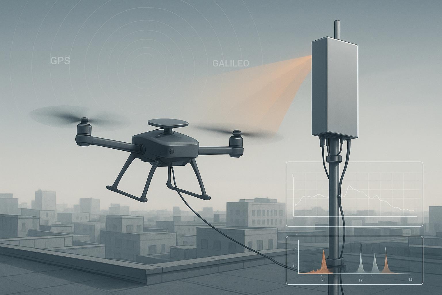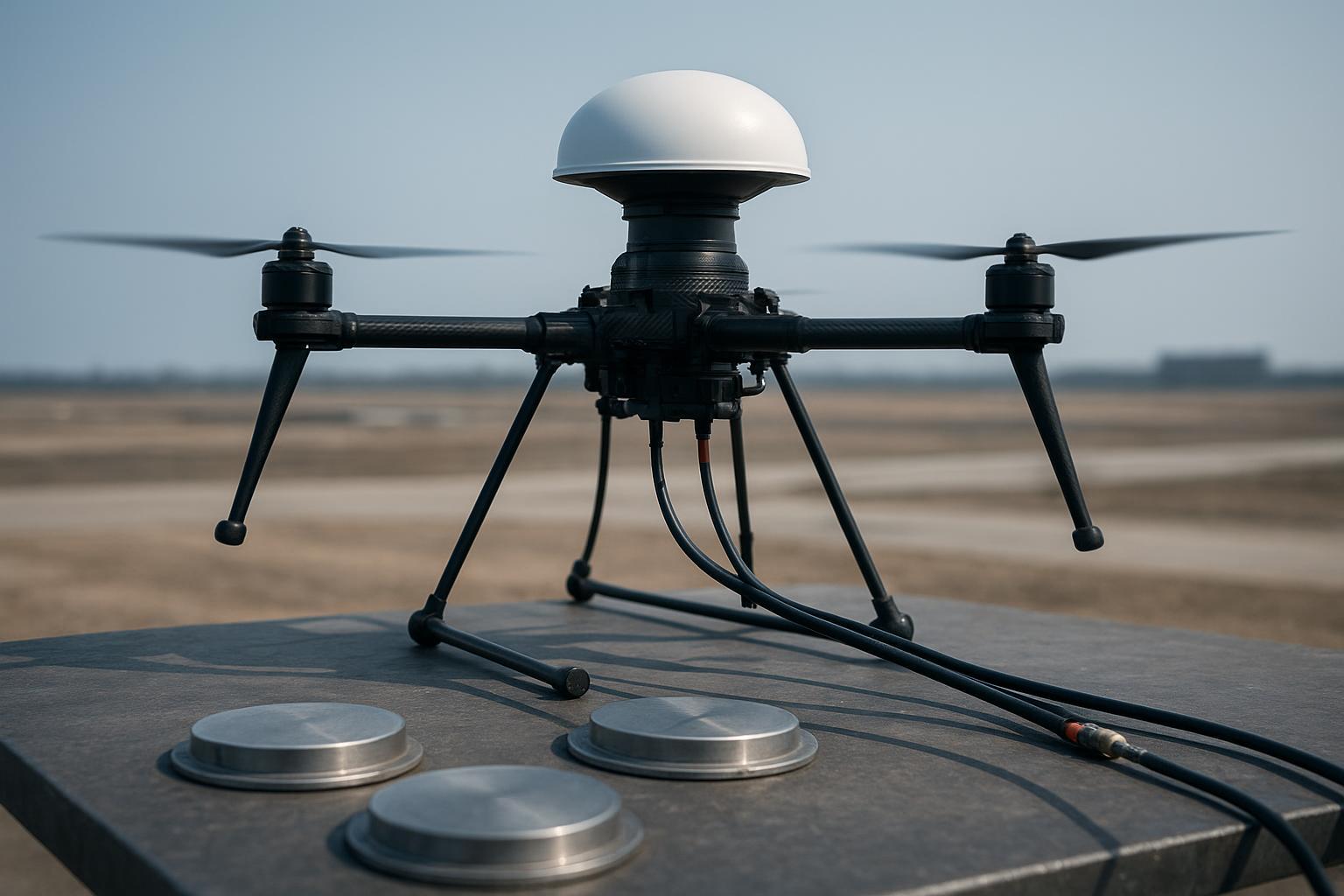
On a summer mapping job, our 4‑kg VTOL lost RTK fixes right as it crossed a power substation fence line. Logs showed per‑satellite C/N0 collapsing by 10–15 dB‑Hz and the receiver’s AGC stepping up: classic interference. Swapping to another survey‑grade patch helped a bit but didn’t stop the fix from dropping whenever the drone faced the substation. What solved it was a compact 4‑element CRPA: the array formed a deep null toward the interference while preserving gain toward satellites, and our fixed solution stayed up through the same pass.
That’s the promise of anti‑jamming GNSS antennas: use spatial filtering at the antenna level to raise your effective J/S margin. This guide explains how CRPA works in practice, where it helps most for RTK drones, and how to specify, integrate, and validate it without getting lost in theory.
Everything in the anti-jamming GNSS antenna library
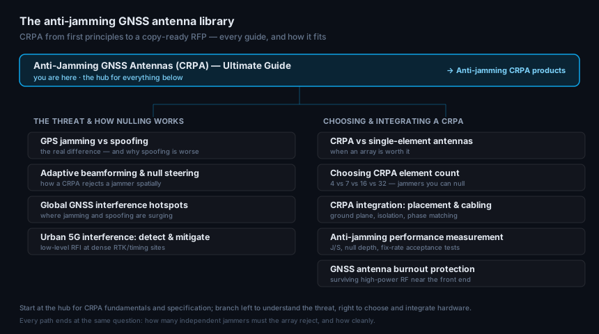
This guide is the hub. Below it sits the full library — branch left to understand the threat, right to choose and integrate a CRPA. Each article links back here.
The threat & how nulling works
- GPS jamming vs spoofing — the real difference, and why spoofing is worse
- GNSS adaptive beamforming & null steering — how a CRPA rejects a jammer spatially
- Mapping global GNSS interference hotspots — where jamming and spoofing are surging
- GNSS interference at urban 5G sites — detecting and mitigating low-level RFI
Choosing & integrating a CRPA
- CRPA vs single-element antennas — when an array is worth it
- How to choose CRPA element count — 4 vs 7 vs 16 vs 32, and the jammers you can null
- CRPA integration: placement & cabling — ground plane, isolation, phase matching
- Anti-jamming performance measurement — J/S, null depth, and fix-rate acceptance tests
- GNSS antenna burnout protection — surviving high-power RF near the front end
When you’re ready to spec hardware, the anti-jamming CRPA antenna line is built for exactly these duties.
CRPA, in practice: beams, nulls, and why calibration rules everything
A Controlled Reception Pattern Antenna is a small array—often 4–7 elements on UAVs—whose signals are combined with complex weights so the array “listens harder” where satellites are and “listens less” where interferers sit. Think of it like cupping your hand around your ear to favor one direction while muffling another, but done in software with phase‑coherent RF.
-
Beamforming and null steering: An adaptive combiner shapes gain toward desired satellites and places one or more nulls toward jammers. In simple terms, with N elements you have roughly N−1 degrees of freedom for nulls per band, subject to geometry and constraints. A gentle primer from Spirent breaks down these ideas without heavy math; see the CRPA concepts in the CRPA Antennas Explained article by Spirent (2024), which clarifies beam/null trade‑offs and testing considerations: Spirent’s CRPA explainer. For a neutral overview of the technique and its use against jamming/spoofing, see the Wikipedia entry on controlled reception pattern antennas: Controlled reception pattern antenna.
-
What performance looks like: In compact arrays typical of UAVs, literature and vendor‑neutral explainers report interference suppression on the order of tens of dB depending on geometry, calibration, and threat type. Peer and vendor‑neutral sources show robust rejection in lab and field demos. For example, Stanford GPS Lab documented adaptive array interference rejection with a 4‑element CRPA in real‑time experiments (ION ITM 2013): Stanford validation of a 4‑element CRPA. Academic work also shows how additional degrees of freedom (including “virtual arrays”) can increase suppression; see Wiggins’ Auburn thesis (2023): Improving CRPA anti‑jamming via virtual arrays.
-
Calibration is everything: Null depth lives or dies on phase and amplitude match, plus a well‑characterized array manifold. As a practical rule, hold cable/chain phase skew to ≤1° at L1 (≤3° often acceptable with some loss), keep element amplitude within ~1–2 dB, and use chamber‑derived steering vectors that include mutual coupling and PCVs. Safran’s test guidance explains alignment practices engineers actually use, such as shared references and coherent sources for calibration: Safran’s engineer’s guide to CRPA testing. For antenna calibration concepts like ARP/PCO/PCV and their mm‑level impact on carrier‑phase positioning, NOAA/NGS provides an accessible reference: NOAA/NGS on GNSS antenna calibration.
Why this matters for RTK on drones
RTK cares about signal quality and continuity more than anything. When a single‑aperture antenna faces a narrowband L1 jammer or a strong broadband noise source, the receiver’s tracking loops lose margin. You’ll see per‑satellite C/N0 drop, AGC rise, and increased cycle slips. An adaptive array can cut the jammer’s spatial contribution while maintaining gain to satellites, preserving carrier‑phase tracking and fix continuity.
Here’s the deal: Anti‑jamming at the antenna level buys your receiver time. That extra J/S headroom often shows up as a higher fixed‑ratio, shorter re‑fix after bursts, and smaller RMSE drift during interference windows. GPS World’s testing overview outlines the core KPIs—C/N0, AGC, fix ratio, reacquisition—that we also use in flight: Testing GNSS receivers against jamming/spoofing. The FAA’s GNSS Interference Resource Guide summarizes threat types and operational impacts relevant to aviation‑adjacent testing contexts: FAA GNSS Interference Resource Guide.
When is CRPA justified for small UAV RTK?
-
Your missions see repeatable interference signatures (AGC steps, C/N0 dips) near infrastructure or in known RFI corridors.
-
Receiver‑side mitigation (filters, notchers, adaptive correlators) isn’t holding fixes in those corridors.
-
Airframe space allows a 4–5 element array and a solid ground plane without compromising CG or prop wash clearance.
-
Regulatory and cost constraints still allow lab‑based validation (simulators/record‑playback) and, where legal, short‑range field testing.
It’s not a silver bullet. Good single‑aperture antennas with sharp front‑ends plus receiver‑side mitigation can be the right trade for low‑threat environments. But if you need reliable RTK through localized RFI, a compact CRPA is often the cleanest way to raise margin without over‑tuning firmware.
The integration mistakes that quietly kill array performance
I’ve seen well‑designed arrays underperform just because basics were missed in the airframe. A few patterns recur.
Ground plane and placement: On small airframes, the ground plane sets pattern stability. As a working target, size the plane to at least ~0.5λ at your highest band when SWaP allows; on compact UAVs, ∅100–150 mm circular planes are a practical starting point. Vendor whitepapers show why edge conditions and plane geometry matter; Tallysman’s note is a useful primer you can verify on your own airframe: Ground‑plane effects on GNSS antennas.
Cable phase mismatch: You can design a beautiful array and lose 10+ dB of null depth to sloppy cabling. Keep per‑element RF chains matched and short. Document residual delays and bake them into the calibration file. Treat ≤1° at L1 as a design target, ≤3° as a line in the sand for many RTK stacks.
EMI and bonding: Self‑noise often masks the benefit you expect from CRPA. Separate RF harnesses from ESC/motor power by inches, cross at 90°, terminate shields 360°, and verify against applicable RE/CE/RS targets (DO‑160 or MIL‑STD‑461 sections where relevant). You’ll be surprised how much a single unbonded panel can radiate into your L‑band path.
Mechanical stability and ARP/PCV discipline: Flexing top plates, tall standoffs, and soft mounts move your array geometry and phase centers. The array’s ARP/PCO/PCV need to be defined and carried into your RTK/INS alignment; this is mm‑level bookkeeping that protects cm‑level results.
Firmware and latency: Some CRPA solutions output per‑element RF; others output a “cleaned” composite RF. Know your latency budget for your specific RTK engine—sub‑microsecond is typically fine; tens of nanoseconds are common in low‑SWaP units. If you’re close to your engine’s limits, characterize it in the lab before chasing gremlins in the field.
Practical improvement checklist for UAV integrators
-
Mechanical and RF layout: Top‑deck mount, rigid base; circular ground plane (∅100–150 mm typical on small airframes), keep metal obstructions out of the field of view; route RF away from power.
-
Cabling and calibration: 50‑ohm low‑loss coax, identical lengths; measure and record per‑channel delay; target ≤1° phase skew at L1 (≤3° max); amplitude match within 1–2 dB; maintain a consistent reference plane.
-
EMI/EMC hygiene: Ferrites/LC on DC rails; 360° shield terminations; star grounds; verify emissions/susceptibility to the program’s DO‑160/MIL‑STD‑461 categories; aim for RF chain noise floors near −140 dBm across 1–2 GHz as a lab baseline.
-
Firmware and interfaces: Confirm whether you’re ingesting per‑element RF or a combined “clean RF”; document latency and any AGC interactions; ensure your receiver keeps full‑rate observables and diagnostics during jams.
-
Validation plan: Use wavefront simulation or record‑and‑playback to prototype; then run a controlled field A/B (where legal) logging C/N0, AGC, fix ratio, TTFF/re‑fix, and RMSE vs. GCPs. Cross‑check with PPK so you can separate positioning engine artifacts from RF effects.
Practical example and test workflow (with acceptance thresholds)
Let’s make this reproducible. Say you’ve got a 4‑kg VTOL mapping UAV with a dual‑frequency RTK receiver (L1/L2). You mount a 4‑element CRPA on a ∅15 cm circular ground plane on the top deck, shielded coax to a low‑SWaP anti‑jam electronics module. For a reference geometry and options overview, see the product summary at GNSource.
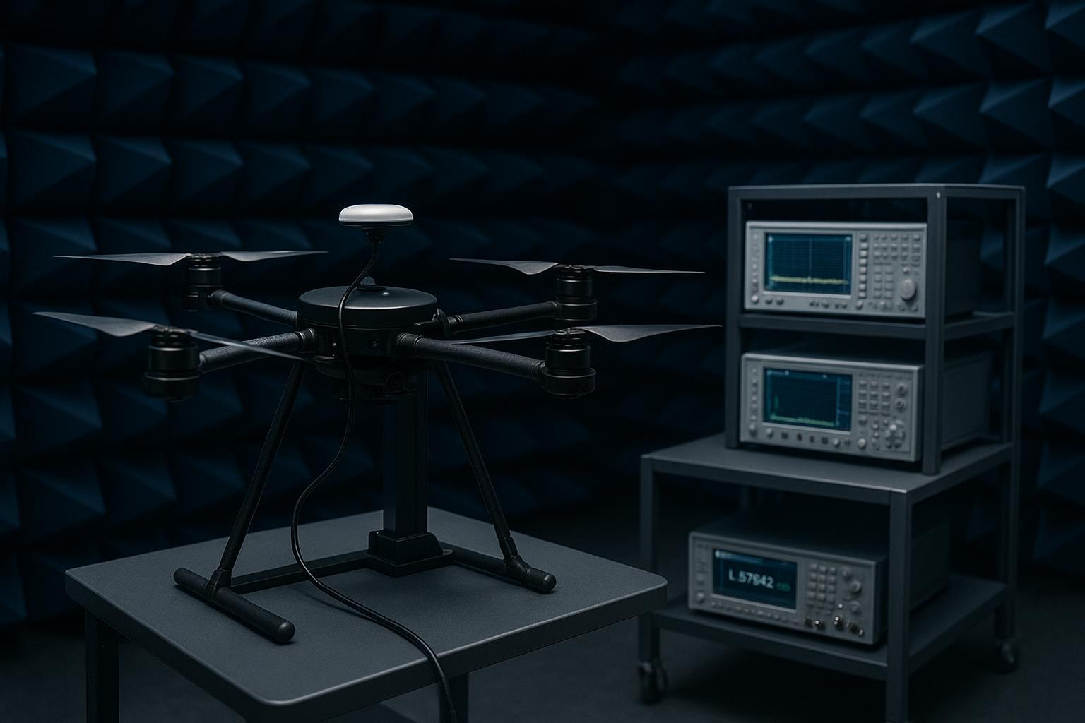
Lab phase: Start with conducted injection or a wavefront simulator to verify basic adaptive nulling and to confirm your calibration file. Sweep both single‑tone and broadband interferers at L1 and L2; log per‑satellite C/N0, AGC, and derived null depths from array weights. Use Stanford’s and Spirent’s conceptual frameworks to sanity‑check what “good” looks like in your logs; e.g., expect tens of dB suppression under favorable geometries and tight calibration, as shown in Stanford experiments and summarized in Spirent’s explainer: Stanford’s adaptive array experiments; Spirent CRPA concepts and testing.
Field phase (authorized site): Place a narrowband L1 emitter at ~1.2 km LOS with timed bursts (e.g., −55 dBm EIRP). Fly a repeatable racetrack. Compare CRPA vs. a survey‑grade single patch:
-
Signal metrics: Per‑satellite C/N0 drop and AGC rise during bursts; satellites tracked vs. used.
-
Position metrics: RTK fixed‑ratio over the pattern, TTFF/re‑fix after each burst, and horizontal/vertical RMSE vs. five GCPs.
Acceptance targets (engineering guidelines, not hard standards):
-
Cable phase match: <1° at L1 ideal; <3° acceptable with some null‑depth loss.
-
Noise floor: Near −140 dBm across 1–2 GHz for the receive chain baseline.
-
RTK continuity: Fixed >90% of epochs under moderate J/S where a comparable single patch falls below ~50% in the same scenario. GPS World’s test KPIs and the FAA guide provide the context for interpreting these numbers: GPS World’s jamming test KPIs; FAA GNSS interference guide.
Legal note: In most jurisdictions, radiating any jammer is illegal without authorization. Favor simulators, anechoic chambers, and record‑and‑playback. Safran’s test guidance describes compliant lab workflows you can adapt: Safran’s CRPA testing guide.
Specifying anti‑jamming GNSS antennas for UAV RTK (copy‑ready RFP)
Below is a compact set of requirements I hand to vendors when we’re down‑selecting. Values marked “guideline” are engineering practices tuned to small UAVs.
Spec item | Target / requirement | Notes |
|---|---|---|
SWaP | ≤500 g; ≤5 W (guideline) | Confirm thermal/vibe (DO‑160/MIL‑STD‑810 categories) |
Bands | Dual L1/L2 minimum; consider L5/E5 | Match receiver and region |
Element count | 4–5 (small UAV); ≥7 if SWaP allows | More DoF, more nulls; geometry dependent |
Interfaces | Per‑element RF or “clean RF” output | Document latency; keep sub‑µs |
Calibration | Factory file with phase/amp, manifold, ARP/PCO/PCV | Include ref freq/temp and re‑cal process |
Ground plane | ≥0.5λ at highest band (guideline) | Circular planes 100–150 mm practical on small UAVs |
Cabling | 50‑ohm, equal length; ≤1° phase skew L1 (guideline) | ≤3° acceptable with some loss |
EMI/EMC | Meet applicable DO‑160/ MIL‑STD‑461 sections | Verify CE/RE/RS levels in platform |
Validation | Lab (conducted + wavefront) + field A/B | Log C/N0, AGC, fix %, RMSE vs. GCPs |
For background reading that informs these choices, a high‑level, neutral CRPA explainer is helpful as a glossary and sanity check: Anti‑jam technology: Demystifying the CRPA (GPS World).
Key takeaways
-
Anti‑jamming GNSS antennas use spatial filtering to suppress interferers while preserving satellite gain; they buy margin that directly shows up in RTK continuity and reacquisition.
-
Calibration dominates performance: target ≤1° phase skew at L1, 1–2 dB amplitude match, and a chamber‑derived array manifold with defined ARP/PCO/PCV.
-
Integration basics matter as much as algorithms: ground plane size/rigidity, cabling, EMI bonding, and mechanical stability.
-
Validate like you fly: lab first (conducted/simulated), then a short, legal field A/B using C/N0, AGC, fix %, and RMSE vs. GCPs.
-
Don’t overspec by reflex: for low‑threat routes, high‑rejection single antennas with receiver‑side mitigation may suffice; reserve CRPA for repeatable RFI corridors or higher‑reliability missions.
FAQ
Q: How many elements do I need on a small UAV? A: Four or five elements are the practical sweet spot for small UAVs, giving useful degrees of freedom for one to two nulls per band without blowing your SWaP budget. Go to seven or more only if space and power allow and your threat model justifies it.
Q: Does CRPA add latency that hurts RTK? A: Low‑SWaP anti‑jam units typically add tens of nanoseconds to sub‑microsecond latency on the RF path, which is well within budget for modern RTK engines. Characterize it in the lab if you’re pushing tight timing.
Q: Will a better single antenna plus receiver‑side mitigation be enough? A: Sometimes, yes. If your interference is mild and intermittent, sharp front‑ends and adaptive correlators may keep you fixed. Use the same KPIs—C/N0, AGC, fix %, RMSE—to decide. When those aren’t enough in known RFI corridors, CRPA is the next lever.
Q: How do I size the ground plane on a compact airframe? A: Treat ≥0.5λ at the highest band as ideal and 100–150 mm circular plates as a practical starting point for small UAVs. Validate with flight logs; some layouts outperform their size due to edge effects and airframe coupling.
Q: Is field jamming testing legal? A: Usually not without specific authorization. Prefer wavefront simulation, record‑and‑playback, or chamber work. The FAA’s interference guide outlines risks and reporting channels.
Q: Where can I read a neutral description of CRPA fundamentals? A: Start with Spirent’s CRPA explainer for practitioner‑friendly concepts and the Wikipedia overview for terminology; use GPS World’s testing guide for KPIs you can measure in your own workflow.
References (selected):
-
Concepts and testing context: Spirent’s CRPA explainer (2024); Controlled reception pattern antenna — Wikipedia
-
Peer/academic examples: Stanford GPS Lab real‑time CRPA validation (ION ITM 2013); Auburn thesis on virtual arrays (2023)
-
Integration/testing guides: FAA GNSS Interference Resource Guide; GPS World jamming/spoofing testing KPIs; Safran engineer’s guide to CRPA testing; Tallysman ground‑plane whitepaper
SEO note: This guide intentionally uses the phrase “anti‑jamming GNSS antennas” in the title, a section header, and contextually throughout to match search intent without stuffing.