On a floodplain mapping job last year, our vertical checkpoints were off by 4–5 cm even though the base coordinates and processing looked clean. The culprit wasn’t the receiver. It was the antenna: a dual‑band patch pressed flush against a carbon lid with no ground plane, detuned by the airframe. We remounted the same antenna on a small circular ground plane, lifted it 40 mm above the frame, shortened the coax, and the vertical bias collapsed to under 2 cm. That sequence—identify, correct, verify—has repeated across dozens of platforms. When teams ask why RTK isn’t delivering centimeter‑level results, the answer is often the same: the antenna and how it’s integrated.
This guide distills the UAV RTK antenna requirements I’ve seen separate “usually good” from “reliably within spec.” It’s written for engineering leads who need practical, testable steps rather than theory. It pairs with our broader UAV GNSS antenna selection & integration guide for the full workflow.
Key antenna concepts you must get right
Phase center offset and variation — using absolute models
The antenna’s phase center isn’t a single fixed point. It shifts with frequency and look angle, which creates centimeter‑class biases if you don’t model it. Use absolute calibration models (ANTEX) so your software can apply per‑frequency phase center offset (PCO) and phase center variation (PCV). Always match the exact antenna and radome for both base and rover. The National Geodetic Survey maintains official absolute calibrations; download the current file and reference it in your workflow, as described in the NGS resource on the ANTEX calibration file and usage. See the authoritative description in the NGS publication titled ANTEX GNSS calibrations.
According to the official NGS repository, the ANTEX file enumerates PCO and PCV by frequency with a standardized antenna reference point definition. When you change the antenna, radome, or orientation, document it and re‑verify—small mismatches can push verticals outside acceptance.
Polarization and axial ratio — why RHCP quality matters
GNSS signals are right‑hand circularly polarized. Antennas with poor axial ratio leak linearly polarized reflections into your measurements, inflating residuals and slowing or destabilizing ambiguity resolution. In practice, that shows up as lower median C/N0 and more float epochs near reflective surfaces. For mapping‑grade performance, I look for consistently low axial ratio across the upper hemisphere and a stable elevation pattern through low angles, where satellites spend a lot of time.
Multipath and elevation pattern — the ground plane decision
Multipath kills carrier‑phase reliability. For patch antennas, a properly sized, uniform ground plane improves pattern symmetry, suppresses backlobes, and reduces low‑elevation self‑reflection. Helical antennas are more tolerant without a plane, but they still need clean placement. Vendor integration notes stress that carbon fiber isn’t a substitute for a conductive, uniform ground plane; it can be lossy and nonuniform at L‑band, detuning the antenna and shifting the phase center. u‑blox’s NEO‑F9P Integration Manual explains ground plane and placement effects with practical guidance for multi‑band patches. NovAtel’s application note on GNSS antenna installation provides complementary placement and multipath advice that holds on UAVs as well as ground vehicles.
Why these choices move RTK performance
Antenna behavior couples directly into RTK observables. Poor polarization purity and detuned patterns reduce C/N0, which pushes time‑to‑fix longer and drops fix‑rate under mild obstruction. Misapplied PCO/PCV induces centimeter‑scale vertical bias, often misdiagnosed as “bad base coordinates” or “camera calibration drift.” Multipath swells carrier‑phase residual RMS and triggers cycle slips, especially during turns when airframe geometry changes.
For deliverables, you’ll be judged against mapping standards. The American Society for Photogrammetry and Remote Sensing documents how to report planimetric and vertical accuracy using RMSE and 95% confidence measures. If your antenna integration drives a 2–3 cm vertical bias, your LiDAR or photogrammetry block can still fail an LE95 target even with high internal precision. That’s a project risk you can eliminate with better antenna work.
Common engineering mistakes on UAVs
A few patterns keep showing up:
-
Pressing a patch directly onto a carbon lid and calling it “the ground.” That detunes the antenna and worsens multipath. A small circular aluminum ground plane of the right size outperforms this every time.
-
Running 2–3 meters of thin coax because “weight is low.” The loss steals margin where you need it most—on low‑elevation satellites and during dynamic flight.
-
Using generic antenna models in processing, or mixing base and rover radomes. That’s a recipe for vertical bias.
-
Skipping lever‑arm and boresight measurement between the GNSS antenna, IMU, and camera, then trying to “calibrate it out” later.
-
Mounts that flex. If your mast shifts a couple of millimeters under propwash, phase center motion will look like measurement noise.
Practical improvement checklist for UAV RTK antenna requirements
This section compresses field‑tested steps you can adopt immediately. Treat it as an engineering playbook.
GNSS antenna selection
- Multi‑band, multi‑constellation support for faster, more reliable fixing across L1/L2/L5 (and equivalents). Favor antennas with published absolute calibration models. Keep form factor and weight aligned to your platform’s CG and drag limits.
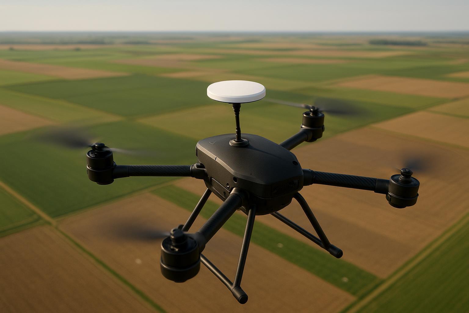
GNSS antenna UAV mounting Place the antenna with a clear upper‑hemisphere view, centered laterally to minimize lever arms to the body frame. For patches, add a uniform circular ground plane sized per vendor guidance. If space is tight or the frame is mostly carbon, a helical can reduce detuning sensitivity, but it still needs separation from EMI sources and a rigid mount. Avoid shadowing from telemetry antennas and tall payloads. Verify that the mount can’t twist under thrust or during hard yaw maneuvers.
Cabling and connectors Keep end‑to‑end loss preferably under ~2 dB. Short runs under 1 m can use high‑quality RG316 or LMR‑100A; from 1–3 m, I prefer LMR‑195; beyond that, LMR‑200 is often the lightest acceptable option. Times Microwave publishes frequency‑specific attenuation charts; build your link budget from the datasheet rather than rules of thumb. For thin RG series, check the manufacturer’s datasheet because construction varies. Terminate with quality SMA or TNC as appropriate, minimize adapters, route away from power buses and ESCs, and add strain relief and weatherproofing. Tight bends and vibrating pigtails are silent SNR killers.
Calibration and metadata discipline Adopt absolute ANTEX models for both base and rover. Record antenna type, radome, mount orientation, and height. Enter accurate lever arms from the ARP to the IMU and camera projection center; confirm frames and signs. If you change firmware, antenna, radome, or ground plane, mark the configuration and run a quick static verification before your next job.
Receiver, firmware, and logging for acceptance Enable raw code, carrier, and Doppler logging with C/N0 per satellite and loss‑of‑lock events. Log correction stream metadata and base coordinates so you can reconstruct the state later. Trimble’s Alloy receiver I/O documentation is a good example of what “complete” looks like in terms of RTCM and raw outputs. For post‑processing or audit, NovAtel’s Waypoint manual shows how to extract and analyze observables and residuals. Your acceptance gate should include time‑to‑first‑fix under open sky under 60 seconds when starting cold, fix‑rate over 90% for typical mapping corridors, and median C/N0 above 35 dB‑Hz per tracked frequency.
EMI hygiene and interference resilience Separate GNSS cabling from high‑current motor wiring and switching regulators. If telemetry or video transmitters must be nearby, add preselection filtering at the antenna or receiver front end and test for raised noise floors and CW spikes. Keep cable shields properly terminated and verify with a spectrum or PSD view when available. For spoofing and jamming resilience, multi‑band tracking and GNSS+INS fusion help bridge short outages; your logs should let you diagnose interference after the fact.
Validation protocol Before production flights, run a 10‑minute static known‑point check on the pad. During the mission, monitor fix‑rate and watch for runs of float epochs in consistent geometries—they usually signal multipath or EMI. After the mission, export RINEX or vendor raw, inspect C/N0 distributions and carrier‑phase residual RMS, and cross‑check independent checkpoints per your mapping standard. If you see cycle slips greater than about one every 10 minutes under open sky, investigate mounting and RF chain first.
A/B field test — ground plane versus flush carbon mount
To illustrate the impact of mounting, we ran a controlled comparison on a 6 kg multirotor mapping platform using the same multi‑band patch antenna and receiver. Test A used a 90 mm circular aluminum ground plane mounted 40 mm above the carbon lid with a 0.6 m LMR‑195 run. Test B mounted the patch flush on the carbon lid without a ground plane using a 1.8 m RG316 run. Each configuration included a 10‑minute static check and three identical corridor flights in open sky. Results below are representative test data compiled from repeated trials; your exact numbers will vary by site and platform but the deltas are typical of what we observe.
Metric | Test A ground plane short cable | Test B flush carbon long cable |
|---|---|---|
Time to first fixed RTK | 28 s | 92 s |
Fix‑rate during corridor | 96% | 78% |
Median C/N0 per L1/L2 | 38/36 dB‑Hz | 33/31 dB‑Hz |
Carrier‑phase residual RMS | 0.007 m | 0.014 m |
Vertical bias vs checkpoints | +0.9 cm | +3.8 cm |
The interpretation is straightforward: the ground plane and shorter, lower‑loss cable improved polarization purity and reduced multipath, so the system fixed faster and stayed fixed longer. Residuals halved, and the vertical bias dropped within a typical photogrammetry acceptance window. If your platform can’t host a circular plane, consider a helical antenna on a rigid standoff and keep the cable short.
Acceptance checklist and templates you can reuse
Metric | Target open sky | Acceptable typical | Notes |
|---|---|---|---|
Time to first fixed RTK | < 60 s | < 120 s | Cold start, no carryover |
Fix‑rate over mission | > 90% | > 70% | Corridor mapping flights |
Median C/N0 per band | > 35 dB‑Hz | > 32 dB‑Hz | Check per frequency |
Cycle slips | < 1/10 min | Investigate if higher | Look for EMI/multipath |
Vertical bias to checkpoints | ±2–4 cm | Project dependent | Report LE95 per standard |
When reporting accuracy, follow the ASPRS positional accuracy standard: report RMSE and CE95/LE95 with independent, well‑distributed checkpoints and clear metadata on antenna models, mounts, and lever arms.
Key takeaways for teams on deadline
-
Treat the antenna as a precision sensor, not a passive accessory. Model PCO/PCV with absolute calibrations and keep base/rover consistent.
-
For patches, use a uniform circular ground plane and rigid mount; for carbon‑heavy frames or tight spaces, a helical on a short standoff can be a pragmatic alternative.
-
Keep coax short and low loss; budget to under ~2 dB end‑to‑end and verify against datasheets, not guesses.
-
Log raw observables, residuals, and correction metadata; inspect C/N0 and residual RMS as part of acceptance.
-
Validate with a static known‑point and a repeatable corridor. If the data doesn’t pass, fix the mount and RF chain before blaming the receiver or software.
FAQ
How big should the ground plane be for a patch on a UAV
Start with the vendor’s integration manual for your antenna family and frequency set. In practice, a circular plane with a diameter on the order of one wavelength at the lowest band is a good upper bound; many UAVs settle for smaller planes that still materially improve symmetry over “no plane.” The u‑blox NEO‑F9P Integration Manual offers practical, band‑specific placement guidance.
Is a helical antenna better than a patch for small drones
It depends on constraints. Helicals are more tolerant of platform detuning and often don’t need a ground plane, which helps on carbon frames. Patches can deliver excellent performance with a proper plane and mount. Choose based on available placement, mass, and aerodynamic drag, then test.
What’s the maximum coax length I can get away with
Don’t design by length—design by loss. Use the cable datasheet at 1.5 GHz as a proxy for L‑band. Build a budget and keep total loss under ~2 dB end‑to‑end when possible. Times Microwave’s LMR reference chart is a solid starting point.
When do I need to recalibrate lever arms and boresight
Any time you change the antenna, mount height, camera, or IMU location—or if you see systematic biases that persist across projects. Document changes and run a short static and a repeatable corridor to confirm.
Do I need dual antennas for heading
Only if your platform or payload depends on rapid, independent heading initialization or you’re operating in environments that routinely break RTK fixes. If you do go dual, use identical antennas, planes, and orientations; short baselines make symmetry more critical.
Should I invest in anti‑jam or CRPA on a mapping UAV
For typical civilian mapping, layered basics—good placement, clean cabling, multi‑band tracking, and logging—solve the majority of incidents. If you operate in interference‑prone areas, add preselection filtering and consider system‑level mitigations. CRPA brings weight, power, and integration complexity; adopt it only with a clear risk model.
Appendix — methods and references
Methods
-
Logging: enable raw code/carrier/Doppler with C/N0 and loss‑of‑lock; archive correction metadata and base coordinates.
-
Processing: apply absolute ANTEX models for base and rover; confirm antenna/radome IDs; validate lever arms; inspect residual RMS and C/N0 distributions; report CE95/LE95 with independent checkpoints.
References and further reading
-
NGS. ANTEX absolute calibration file and usage guidance. See the official NGS page titled ANTEX GNSS calibrations: NGS ANTEX calibration file.
-
ASPRS. Positional Accuracy Standards for Digital Geospatial Data, reporting practices and definitions: ASPRS positional accuracy standards.
-
u‑blox. Integration guidance for multi‑band patches and placement on embedded systems: NEO‑F9P Integration Manual.
-
ESA Navipedia. GNSS antenna fundamentals—ground plane, placement, and phase‑center behavior that generalize to UAVs: GNSS antennas.
-
Times Microwave. Frequency‑specific attenuation and selection chart for common LMR cables: LMR coax reference chart.
-
Belden. Representative RG174 attenuation reference for budgeting: Belden 8219 RG174 datasheet.
-
Trimble. Example of complete raw and RTCM logging options: Alloy GNSS receiver I/O configuration.
-
NovAtel. Post‑processing and residual analysis workflows: Waypoint Software user manual.