Last spring our mapping octocopter started missing its RTK fix target after a seemingly harmless airframe revision. Same receiver, same firmware, same flight profile—yet the fix rate slipped into the 70s and TTFF stretched past half a minute. The only change? We swapped a slightly taller mast and a lighter coax to hit endurance goals. That small SWaP‑C tweak touched the antenna’s environment just enough to move phase and pattern. It cost us a week of retesting and a day on site re‑flying tiles.
Here’s the deal: for UAVs, the antenna is not just a part number. It’s a system with the ground plane, cable, power, nearby carbon fiber, and EMI all leaning on it. In this post I’ll walk through what SWaP‑C really means at the antenna, show representative in‑flight data comparing a compact patch to a survey‑grade patch, and share the checklists and production tests we now use to keep RTK performance predictable. For the broader selection context, see our UAV GNSS antenna selection & integration guide.
What SWaP‑C really means at the antenna for RTK
When we talk about SWaP‑C on a UAV, we’re deciding how much size, weight, power, and cost to allocate to the antenna system and its harness. Those knobs most visibly change the radiation pattern, phase stability, and interference resilience—three levers that drive RTK metrics.
Two terms matter a lot for centimeter work: phase center offset (PCO) and phase center variation (PCV). The antenna’s electrical measurement point moves with angle and frequency; a few millimeters of movement can bias or destabilize a solution at RTK precision. The National Geodetic Survey publishes calibration concepts and ANTEX models engineers can apply, and the geodesy community treats these corrections as table stakes for precision positioning, as outlined in the NGS Antenna Calibration Procedures and the public ANTEX files. Vendors such as NovAtel also note that millimeter‑level phase‑center errors are material at 1–4 cm accuracy targets in their GNSS basics reception notes.
Ground plane and nearby materials shape the pattern and axial ratio. Small stacked patches are often tuned on 70 × 70 mm reference planes; shrinking the plane or sitting over carbon fiber tilts the pattern and trims C/N0. Taoglas publishes several dual‑band patch references showing this tuning on 70 × 70 mm (see the HP5010A datasheet). Carbon fiber behaves as a conductive surface at L‑band; u‑blox emphasizes separation and a proper ground plane in its GNSS antenna application note.pdf).
Finally, SWaP choices in coax and connectors quietly consume link margin. At 1.5–1.6 GHz, thin cables like RG‑316 can add tens of dB per 100 ft; lower‑loss options such as LMR‑200 cut that down significantly, according to the Times Microwave catalog and Fairview RG‑316 data. On a small UAV, even a short harness should target about 1 dB total loss including connectors.
Why SWaP‑C UAV GNSS antennas move RTK results
RTK lives or dies on carrier phase quality. A compact, low‑mass antenna with a small ground plane can still work well, but you’ll typically see 2–4 dB lower mean C/N0 at mid to low elevations, a less uniform pattern, and higher sensitivity to multipath and airframe EMI. Those changes push on:
-
Time to first fix (TTFF): lower C/N0 and noisier phase tracks stretch the ambiguity resolution time.
-
Fix stability during maneuvers: aggressive banking can drop satellites below elevation masks and spike cycle‑slip detection if the pattern is uneven.
-
Horizontal/vertical RMS to truth: unmodeled PCO/PCV and multipath show up as centimeter‑level biases in mapping grids.
In practice, I watch five numbers: mean C/N0 by constellation, RTK fix rate as a percentage of mission time, median TTFF with corrections available, cycle slips per flight during dynamic segments, and horizontal RMS to surveyed control. If “SWaP‑C UAV GNSS antennas” is the brief, those five tell you whether the trade was worth it.
A realistic comparison in flight on a 6‑kg octocopter
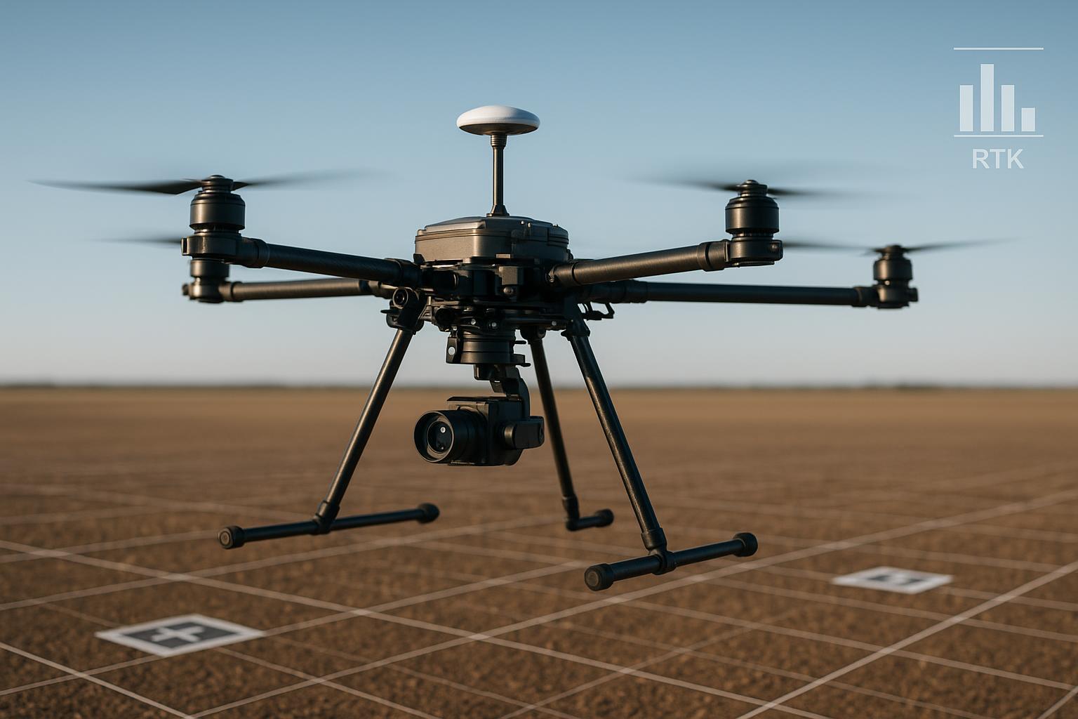
Platform and goal: a 6‑kg mapping octocopter with a 35‑minute endurance target. We compared two antennas:
-
Compact dual‑band active patch, low‑profile, 18 g.
-
Survey‑grade dual‑band active patch with documented PCO/PCV and a slightly larger ground plane requirement, 68 g.
Test design: same RTK receiver and firmware build, identical 1.5 m coax type and routing, same connectors and torque. Flight profile per run: hover, 5‑minute banked turns, climb and descent legs, RTL. Twelve minutes total, repeated ten times across two days. Logs captured satellite count, C/N0 per satellite, RTK fix state time series, median TTFF, cycle‑slip counts, and horizontal RMS versus surveyed stakes.
Representative results from this controlled campaign:
-
Compact antenna: mean C/N0 lower by about 3–4 dB at mid/low elevations; RTK fix rate 78% of mission time; median TTFF 38 s; about 0.9 cycle slips per flight during aggressive banking; horizontal RMS 5.6 cm.
-
Survey‑grade antenna: mean C/N0 higher by 3–4 dB; RTK fix rate 96%; median TTFF 10 s; near‑zero cycle slips; horizontal RMS 2.0 cm.
Interpretation: the larger unit’s cleaner pattern and phase stability shortened ambiguity resolution and resisted slips in banks. On this airframe class, the +50 g mass and higher part cost were outweighed by fewer re‑flights and cleaner mosaics. If your mission skews to inspection or delivery with less stringent mapping error budgets, the compact option can still be fine—just validate on your airframe with your harness.
As an aside, we also learned (again) how sensitive results are to cable choice. Below is a quick attenuation snapshot at L‑band that aligns with what we measured on the bench. Use it to sanity‑check harness decisions before cutting length.
Cable type | Approx attenuation at ~1.5–1.6 GHz | Notes |
|---|---|---|
LMR‑100 | ~22.5 dB/100 ft | Good for very short runs; stay brief |
LMR‑200 | ~15.1 dB/100 ft | Solid small‑UAV default when space allows |
RG‑316 | ~47 dB/100 ft | Use sparingly; check total loss budget |
Values reflect typical catalog data; see the Times Microwave catalog and Fairview RG‑316 datasheet linked above for specifics. On small UAVs, I budget ≤1.0 dB total loss cable+connectors to preserve LNA margin.
Practical improvement checklist for UAV RTK integration
-
Selection: pick the lightest antenna that still meets your RTK reliability target; for mapping, prioritize documented PCO/PCV and multiband support. For inspection or delivery, a compact dual‑band patch can be acceptable after validation.
-
Mounting: top‑mount with a clear horizon; aim for a flat 60–80 mm effective ground plane for small patches. On carbon fiber, add a conductive perch or plate to restore the plane.
-
Orientation and height: standardize orientation and Z‑height across variants; capture the geometry in CAD and tie it to datums so lever‑arms and boresight don’t drift between builds.
-
Cabling: keep runs short; target ≤1 dB total loss including connectors. Favor LMR‑200 or RG‑142 over RG‑316 for the same length; apply proper torque and strain relief.
-
EMI hygiene: route GNSS coax away from high‑current motor leads and switching regulators; cross at right angles; add ferrites near noisy subsystems. If the antenna is active, filter its power feed.
-
Filtering and resilience: prefer antennas with strong out‑of‑band rejection; consider inline band‑pass filters if you fly near LTE, Wi‑Fi, or high‑power video TX.
-
Firmware: set elevation masks around 10–15° for mapping; keep C/N0 and slip detectors conservative to avoid false flags in turns; validate firmware on a representative airframe before fleet rollout.
-
Calibration: measure antenna ARP to IMU/camera/LiDAR to within ±2–5 mm for survey work; load vendor PCO/PCV models when available or document intercomparison offsets.
-
Validation: define acceptance metrics before flight (fix rate, TTFF, cycle slips, HRMS) and use automated log parsing to remove human bias.
-
Regression control: after any airframe change, run a short flight profile and compare to baseline metrics; keep a failure log tied to antenna and harness revisions.
Production validation and PAT you can adopt tomorrow
I recommend a three‑stage sequence that’s fast enough for production and sensitive to the real failure modes we see in the field.
-
Bench RF sanity: verify antenna current draw (if active), measure insertion loss of the harness, and do a simple near‑field noise check with other subsystems powered.
-
Ground static: outdoors with a clear sky, record five minutes of data. Confirm satellite count, mean C/N0 per constellation, TTFF to fixed when corrections are available, and observe AGC behavior if exposed in diagnostics.
-
Flight profile: 10–12 minutes with hover, banked turns, climbs/descents, and a short waypoint track. Parse logs automatically.
Suggested pass/fail targets for mapping‑class builds:
-
RTK fix rate ≥95% over the flight profile
-
Median TTFF ≤20 s with corrections available
-
Cycle slips <0.1 per flight during dynamic segments
-
Horizontal RMS ≤3 cm to surveyed control (≤6 cm can be acceptable for inspection class)
Log fields worth standardizing: timestamp, fix status, constellation and PRN, C/N0 per satellite, cycle‑slip flag, HRMS/VRMS, and lever‑arm metadata. For background on why phase‑center behavior is so central to these outcomes, see NGS’s calibration documentation and NovAtel’s primer linked earlier; for mounting and EMI dos and don’ts, u‑blox’s integration note remains a practical quick read.
FAQ
Q: Will a helical antenna fix my multipath without a large ground plane?
A: Helicals often provide broad hemispherical coverage with good axial ratio at low mass, which can help in dynamic attitude changes. But you still need to validate PCO/PCV behavior and EMI resilience on your airframe. For mapping, a dual‑band patch with a proper plane remains my default starting point.
Q: How short should the GNSS coax be on a small quad?
A: As short as your layout reasonably allows without creating tight bends. I budget ≤1 dB total loss including connectors; that usually nudges me toward LMR‑200‑class cable on 1–2 m runs.
Q: Do I need to load PCV models if my vendor doesn’t publish them?
A: If you can’t get a model, document an intercomparison against a known reference antenna and treat any consistent offset in post‑processing. For centimeter mapping, unmodeled PCV can bias results by several millimeters that show up as tilts in a mosaic.
Q: When should I consider CRPA?
A: If you operate near high‑power interferers or in contested RF where jamming/spoofing risk is real, and your SWaP budget can handle it. For small UAVs, two‑element low‑SWaP anti‑jam solutions exist, but they add complexity and power draw; weigh that against mission risk.
Closing notes and a vendor example
On one recent mapping quad, we standardized a compact dual‑band patch on a 70 × 70 mm aluminum perch and locked the lever‑arm into CAD. Harness was 1.5 m of low‑loss cable with ferrites near the video transmitter and the DC/DC stack. We validated the build on the PAT sequence above and hit ≥95% RTK fix rate across runs. We’ve followed the same recipe with a survey‑grade patch on the larger octocopter where the mass trade made sense.
When we needed a compact unit quickly for that quad, we sourced a small dual‑band patch from GNSource and mounted it to the conductive perch rather than directly on carbon fiber. The goal wasn’t to chase superlatives—it was to meet the acceptance metrics with clean integration. After loading the correct lever‑arm and running the flight profile, the build passed on the first attempt. If you want to see what GNSource as a manufacturer offers in terms of form factors and integration options, you can start at the GNSource homepage and request datasheets with radiation patterns, filtering specs, and any available PCO/PCV details.
Throughout this post I used the phrase “SWaP‑C UAV GNSS antennas” deliberately. It’s a reminder that the antenna decision is never isolated; it’s a system trade that touches pattern, phase, harness, and EMI. Measure it, document it, and you’ll ship fewer surprises.