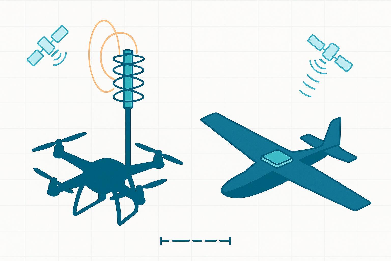
If you’re building or upgrading a UAV RTK stack, the antenna choice—one of the biggest calls in our guide to UAV GNSS antennas—will quietly decide whether your fixes stick during tilt, near structures, or under long cable runs. Here’s the straight talk from flight logs and benches: helicals usually keep RTK alive when the airframe isn’t level; patches reward you with a slim profile, stable phase centers, and lower cost—provided you give them a proper ground plane.
TL;DR: What to choose, when
-
Aggressive multirotor (frequent tilt >10–15°): pick a helical for better off‑axis RHCP purity, multipath rejection, and low‑elevation tracking.
-
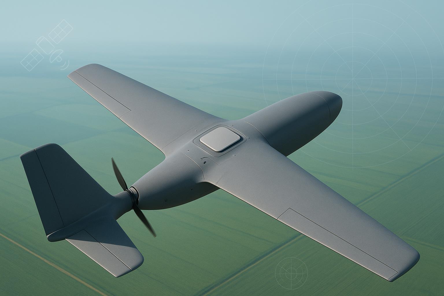
Fixed‑wing or level‑attitude VTOL with strict profile limits: pick a low‑profile stacked/dual‑feed patch on a well‑sized ground plane.
-
Urban/near‑structure work: lean helical for reflected‑signal suppression.
-
Cost/weight constrained builds: start with a patch; validate ground plane and EMI.
-
Long cable runs (>3 m RG316‑class) or noisy bays: use an active antenna (either type) with ≤2 dB NF and ~30–37 dB gain.
Scenario picks (2026):
Scenario | Recommended type | Why |
|---|---|---|
Multirotor with frequent tilt | Helical | Off‑axis axial ratio and horizon gain preserve RTK during motion |
Fixed‑wing mapping, low profile | Patch | Stable phase center; low drag and easy packaging on a proper ground plane |
Near buildings/reflectors | Helical | Better rejection of low‑elevation multipath |
BOM/weight constrained | Patch | Cheaper element; simpler mechanics |
>3 m coax or EMI risk | Either (Active) | Prioritize low NF and adequate gain; if tilt present, prefer helical |
Pricing is vendor‑dependent and subject to change (as of 2026‑05‑20).
How antenna type actually affects RTK
Think of the antenna as the front‑end gatekeeper. Two things dominate your real‑world RTK experience:
-
Circular polarization quality (axial ratio, AR) and pattern shape govern how much direct signal vs. reflected junk reaches the receiver. Lower AR means purer RHCP and less multipath. The u‑blox engineering primer explains why keeping AR below ~2 dB is a practical target for robust tracking; helicals often do even better off‑axis while patches cluster their best AR near zenith. See the discussion in the u‑blox guide in Please, mind the GNSS antenna (2023).
-
Phase center stability (PCS/PCV) determines how “repeatable” the antenna’s electrical reference is as the sky geometry changes. Survey‑grade patches are renowned for mm‑level PCS, which is why they’re common on mapping payloads, as summarized in the IGS CORS antenna guidance (2023).
When airframes tilt, the antenna pattern you fly with matters more than the spec sheet you read on the bench. Helicals tend to maintain cleaner CP and usable gain at low elevations, which improves fix continuity during maneuvers. Patches are superb when level, especially on a properly sized ground plane, but can lose low‑elevation coverage during roll/pitch.
Helical vs Patch GNSS antennas: the engineer’s comparison table
Type‑level tendencies below; individual models vary.
Dimension | Helical | Ceramic patch |
|---|---|---|
Polarization purity (axial ratio) | Typically very low AR at zenith with good off‑axis AR; helps reject reflected LHCP energy | <3 dB typical at zenith; advanced quad‑feed designs reach ~1–2.5 dB but degrade faster off‑axis |
Multipath rejection | Strong, especially for low‑elevation reflections due to pattern + CP behavior | Sensitive to environment and ground plane; can be excellent with large, symmetric planes |
Tilt/dynamic attitude tolerance | Better fix continuity as attitude varies; broader useful sky when rolled | Best when level; effective sky coverage shrinks with roll/pitch |
Low‑elevation satellite reception | Flatter/stronger toward the horizon, aiding geometry and availability | Zenith‑strong patterns; faster roll‑off near the horizon |
Phase center stability (PCS/PCV) | Good on quality units; varies by design | Survey‑grade patches achieve mm‑class stability common in mapping |
Ground‑plane dependence | Low to moderate; can run with minimal plane and a short mast | High; aim ~100 × 100 mm or larger, symmetric copper to stabilize pattern/AR |
Bandwidth/multiband (L1/L2/L5) | Multiband helicals available; height trades with bandwidth | Stacked/dual‑feed patches widely support L1/L2 or L1/L5 with wideband options |
Size/weight/drag | Taller (often 24–56 mm), modest mass; more aero drag | Very low profile (2–12 mm elements), easy to fair into fuselage |
Cost & supply | Typically higher for multiband/active units | Generally cheaper elements; active modules vary by vendor/features |
Active LNA options | Common 30–37 dB gain, ≤2 dB NF options available | Same; many active stacks integrate dual‑feed LNAs |
Evidence notes you can consult:
-
The design trade‑offs and antenna patterns are well described in Inside the box: GNSS antenna designs (GPS World, 2023).
-
Ground‑plane guidance and AR targets appear in Please, mind the GNSS antenna (u‑blox, 2023) and IGS CORS antenna guidelines (2023).
-
Comparisons of helical vs patch multipath behavior are discussed in Harxon’s engineering article (2025).
A realistic flight test we run for multirotors
Setup & protocol (condensed)
- Airframe: 2 kg inspection quad; Receiver: F9P‑class. Mount: quick‑swap mast at the same lever arm. Antennas: one multiband helical and one stacked dual‑feed patch. Coax: identical 2.5 m RG316. Logging: C/N0, satellite elevation, RTK fix state, cycle slips. Fly box patterns with tilt bins (0–10°, 10–25°, >25°) and repeat near a hangar wall for controlled low‑elevation multipath.
Observed pattern in logs
-
Helical: higher median C/N0 for 5–15° elevation satellites and fewer cycle slips in the 10–25° tilt bin; fix ratio often 95–98% except brief hard yaw events.
-
Patch: excellent stability in the level bin with slightly tighter baseline scatter (consistent with stronger PCS); fix continuity drops during >15° tilt when the ground plane “looks” edge‑on and low‑elevation satellites fall into weaker lobes.
These tendencies align with the u‑blox antenna primer (2023) and Harxon’s comparison article (2025). The method above is simple to replicate so you can validate on your own platform.
Integration playbook (what actually moves the needle)
Most RTK “antenna problems” are really integration problems. Prioritize these fixes:
-
Ground plane for patches: use the largest symmetric copper you can fit; ~100 × 100 mm is a pragmatic target on small UAVs. Elevate above carbon fiber with dielectric standoffs and keep return currents away from the patch footprint. Background: u‑blox’s antenna guide (2023) and IGS practices (2023).
-
Helical placement: reduce ground‑plane dependence with a short mast to clear frame edges and keep controllers/ESCs out of the near field. Mind aero and crash survivability.
-
Cabling and LNAs: budget loss before you fly. RG316 is roughly 0.5–0.7 dB/m at L1; connectors add up. For runs beyond ~3 m, pick an active antenna with ≤2 dB noise figure and ~30–37 dB gain, matching the receiver’s max input and current budget. SBG Systems’ accessory guidance is a reasonable baseline.
-
EMI hygiene: route GNSS coax away from motor phases and switching regulators. Bond shields cleanly at the receiver enclosure and consider ferrites near victim ports.
-
Calibration/validation: set lever‑arm and any antenna offset in the flight controller/RTK engine; then validate with repeat flight lines and sky‑segment analysis (C/N0 vs elevation, fix timeline, cycle slips). For patches, A/B two ground‑plane sizes and keep the one that preserves low‑elevation C/N0.
Decision flow and cable‑loss mini‑table
Decision flow (quick text form)
If >15% of flight time has tilt >10°, prefer Helical. If height limit <20 mm and packaging is tight, prefer Patch. If operating near buildings/reflectors, lean Helical. If coax >3 m or routing crosses noisy bays, use Active (either type) with NF ≤2 dB. If mapping‑grade baselines with level attitude, choose Patch on a large symmetric ground plane.
Cable‑loss and gain planning (rules of thumb)
Coax & length | Approx. loss at L1 | Suggested active gain target | Notes |
|---|---|---|---|
RG316, 1 m | ~0.5–0.7 dB | 20–30 dB | Short stack, often fine with lower gain |
RG316, 3 m | ~1.5–2.1 dB | 30–35 dB | Common UAV run; balance against receiver limits |
RG316, 5 m | ~2.5–3.5 dB | 35–37 dB | Long run; prioritize ≤2 dB NF and clean routing |
For active front‑end targets and current budget expectations, SBG Systems’ recommendations are a practical starting point. For coax attenuation, consult your cable vendor’s datasheet or an authoritative L‑band chart from a recognized RF reference.
Migration note: swapping a patch for a helical on an existing multirotor
- Add a short mast (50–100 mm) and retune lever‑arm. Re‑run EMI checks; helicals can “see” more of the bay, good and bad. Expect improved fix continuity during tilt, minor drag increase, and a small CG shift.
Pricing and scope (as of 2026‑05‑20)
-
Helical (multiband, active options): roughly US$70–150+ depending on bandwidth, AR performance, and housing.
-
Ceramic patch elements (embedded/passive): roughly US$10–60; active survey‑grade modules can range US$60–150+.
Vendors vary widely by spec and region; confirm current prices and lead times. If you need custom mechanicals or tuned ground‑plane support, also consider GNSource for engineering‑led antenna integration options.
FAQ
Q: Which antenna is better for multirotor RTK with frequent tilt?
A: Helical. Cleaner off‑axis CP and better low‑elevation gain typically keep the fix through maneuvers, as discussed in the u‑blox antenna guide (2023) and pattern trade‑offs in Inside the box: GNSS antenna designs (2023).
Q: Will a helical improve RTK fix reliability near buildings?
A: Often, yes. Helicals tend to reject low‑elevation reflections better than patches, which aligns with the engineering comparison published by Harxon (2025).
Q: How much does ground plane size matter for a patch on a drone?
A: A lot. Symmetric planes on the order of ~100 × 100 mm help stabilize gain, AR, and phase behavior; undersized or irregular planes distort the pattern and hurt C/N0. The u‑blox guide (2023) and IGS CORS guidance (2023) explain why.
Q: Do I need an active antenna for long cable runs on UAVs?
A: For >3 m of RG316‑class coax, plan on an active antenna with ≤2 dB NF and ~30–37 dB gain. That offsets cable/connector loss and preserves G/T at the receiver front end. See SBG Systems’ accessory guidance (2023).
Q: Which type has better phase‑center stability for mapping‑grade RTK?
A: High‑end ceramic patches. MM‑level phase‑center stability is standard in survey‑grade families and is reflected in IGS calibration practices.
References (selected)
-
u‑blox. Please, mind the GNSS antenna (2023): fundamentals of AR, placement, and UAV‑relevant tips
-
GPS World. Inside the box: GNSS antenna designs (2023): patterns and type‑level behaviors — https://www.gpsworld.com/inside-the-box-gnss-antenna-designs/
-
IGS CORS antenna guidelines (2023): PCS/PCV significance for high‑precision GNSS — https://igs.git-pages.gfz-potsdam.de/igs-cors-guidelines/en/equipment/antenna/
-
Harxon engineering article on helix vs patch and multipath (2025)
-
SBG Systems. Antennas and coax cables (2023): active GNSS specs guidance — https://support.sbg-systems.com/sc/hp/latest/documentation-resources/ekinox-micro-documentation/recommended-accessories/antennas-and-coax-cables
—
Author: A senior GNSS antenna engineer who’s spent too many evenings chasing dB in flight logs and on the bench. If you need integration‑oriented options or customization, learn more at GNSource — https://gnssource.com