When an RTK platform works great on the bench but drops to float during yaw or under throttle, it’s almost never “mystery GNSS.” It’s integration. Over the last few years, we’ve flight‑tested RTK receivers on quads, hexes, and a couple of heavy‑lift frames built around carbon composite decks. The pattern is consistent: placement, ground‑plane discipline, carbon proximity, and EMI control determine whether you hold a rock‑solid fix—or spend the mission watching the estimator fight.
Below is a field‑tested guide to GNSS antenna placement on drones—what actually moves C/N0, fix ratio, and cycle slips—and how to design mounts that scale from prototype to production. I’ll keep the theory light and the recommendations measurable. Placement is one layer of the fuller UAV GNSS antenna selection & integration guide.
What actually controls GNSS performance on drones
Four levers control your link budget and RTK stability on a UAV:
-
Sky view and self‑shadowing: The antenna needs an unobstructed hemisphere. Recessing a patch under carbon or near tall masts clips low‑elevation satellites and distorts the pattern.
-
Local ground plane under patches: Size, continuity, and bonding drive pattern symmetry, polarization purity, and multipath rejection. u‑blox’s GNSS Antennas application note (2018) explains how patch performance tracks ground‑plane size and centering on real boards; their integration manuals suggest ~50–70 mm local planes as practical targets for compact patches. See the vendor guidance in the GNSS Antennas Application Note by u‑blox (2018). I link it here for context: the detailed ground‑plane guidance is in the u‑blox GNSS Antennas Application Note (UBX‑15030289).pdf).
-
Carbon‑fiber proximity: CFRP behaves like a lossy conductor at L‑band. Placing a patch close to a carbon deck shifts resonance, alters impedance, and soaks energy—measurably dropping C/N0. The mechanism is consistent with modeling and measurement practices summarized in the U.S. NTIA’s antenna‑near‑structure work; see the NTIA TM‑13‑489 antenna modeling report.
-
Platform EMI: ESCs, DC‑DCs, high‑power radios, and long battery leads spray broadband noise. Separation, routing, ferrites, and shielding are your workhorses. Community autopilot docs emphasize moving GNSS away from high‑current wiring and consolidating ESCs; ArduPilot’s practical write‑up remains a good operational checklist; see ArduPilot’s magnetic/interference guidance.
Carbon fiber and ground planes: what to do on real airframes (GNSS antenna placement drones)
Here’s the approach that’s worked across multiple carbon frames:
-
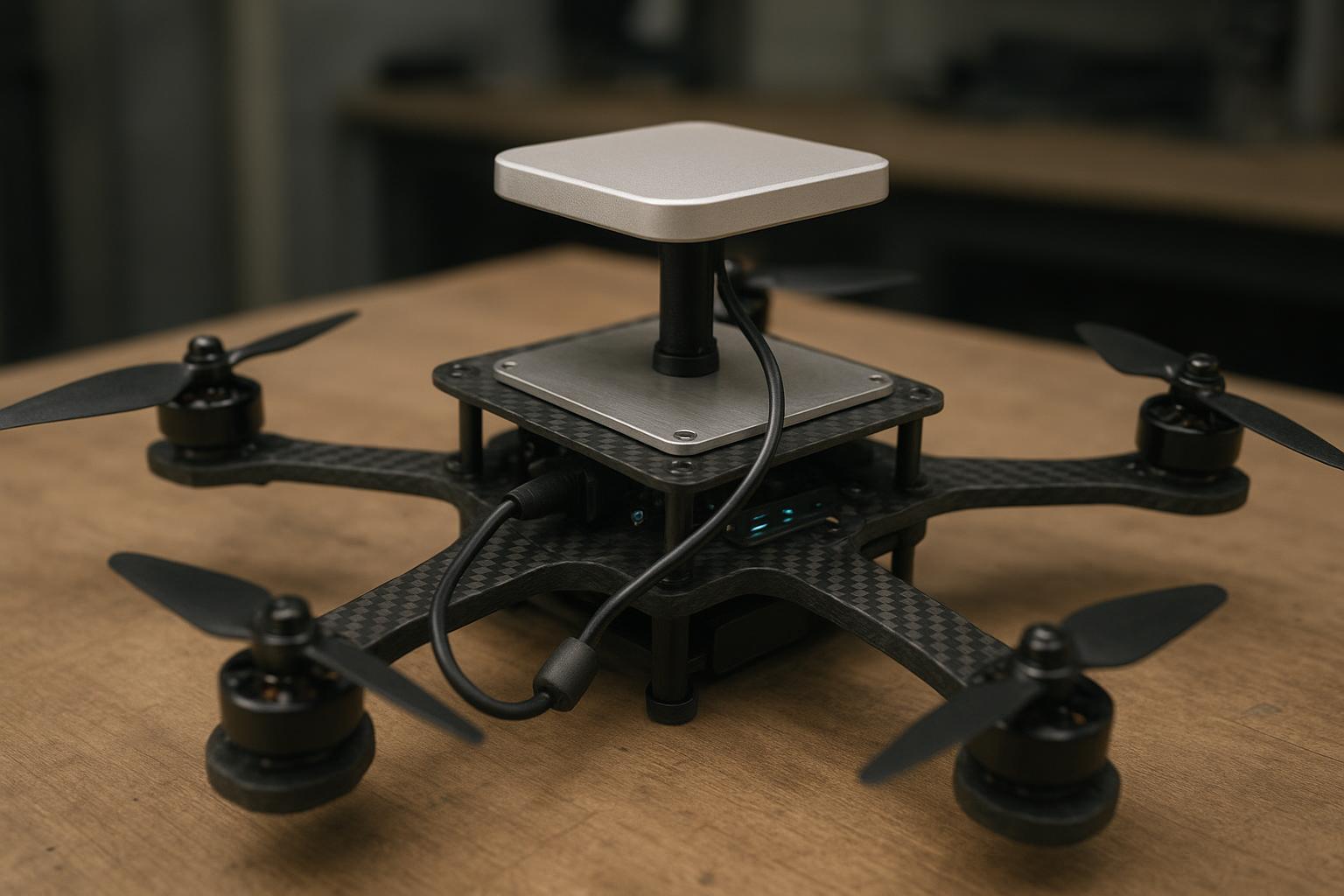
Use a non‑conductive standoff between the patch and the carbon deck. We’ve had repeatable results with 15–25 mm. Below ~10 mm, carbon coupling starts to detune small L1/L2 patches.
-
Add a bonded metallic local ground plane directly under the patch when the airframe is carbon. On sub‑2 kg quads, an 60–80 mm square aluminum or copper plate bonded to system ground stabilizes the radiation pattern and reduces pattern skew in yaw.
-
Target ground‑plane extents of ~50 × 50 mm to 70 × 70 mm (or larger if you can afford the area). That aligns with compact module guidance from u‑blox and with several Tallysman patch datasheets that show better C/N0 when a small built‑in plate is augmented by a larger local plane. Tallysman explicitly notes this for its 25 mm dual‑feed line; see the Tallysman TW1722 datasheet.
-
Keep the plane continuous and well‑bonded. If the “plane” is a PCB area, stitch outer copper to inner ground with dense vias to keep RF return impedance low. NovAtel’s hardware notes highlight continuous ground and via stitching for RF integrity; the OEM7 family data captures the gain budget expectations; see the NovAtel OEM7500 data sheet.
Why it matters: on carbon frames we routinely measure 1–3 dB‑Hz median C/N0 deltas from these details alone. That’s enough to swing fix ratio during dynamic segments.
EMI you can’t ignore
EMI mitigation is a hierarchy: separation first, then routing, then filtering, then shielding/grounding. In practice:
- Separate the GNSS antenna and feedline from ESCs, motor phase wiring, DC‑DC modules, and high‑power radios. Keep GNSS coax away from parallel runs of battery leads; cross at right angles. Add clip‑on ferrites where the coax enters the receiver enclosure and where power harnesses leave noisy modules. The ArduPilot community doc linked earlier has pragmatic layout calls, and NovAtel’s installation guides emphasize proper grounding and chassis bonding; refer to the NovAtel CPT7/CPT7700 quick start (2023) for grounding/bonding cues.
If you still see RTK degradation correlated with throttle or yaw, put a spectrum analyzer or receiver IF monitor on the bench and look for harmonics around L1/L2 bands. Often you’ll find a DC‑DC spur or VTX harmonic landing in‑band.
Cabling and connectors that don’t silently kill RTK
Loss budgets on small airframes are tight. Keep the antenna feed short and choose coax intentionally. Approximate attenuation at ~1.575 GHz (from vendor curves):
Cable type | Attenuation at ~1.575 GHz (dB/m) | Notes |
|---|---|---|
RG‑178 | ~1.0–1.2 | Thin, flexible PTFE coax; higher loss than RG‑316. Data per Times Microwave curves in their catalog. |
RG‑316 | ~0.9–1.1 | Common UAV harness coax; moderate loss (Times Microwave). |
~1.13 mm micro‑coax | ~1.2–1.6 | Very compact; highest loss; confirm with the exact datasheet (e.g., StripFlex II). |
Reference curves are published by Times Microwave; see the Times Microwave attenuation tables and the StripFlex II micro‑coax datasheet.
Connector choices (SMA/FAKRA/MCX) are secondary to strain relief and sealing. We specify torque on SMA pigtails, anchor the coax near both ends to prevent microphonics, and avoid tight bends at the antenna base.
On active antennas, ensure cascaded gain meets the receiver’s expectation. NovAtel’s OEM7 documentation cites a nominal cascaded GNSS antenna gain target around 26–30 dB (≥20 dB minimum). If you run long or lossy coax, you may quietly dip below that and pay for it in cold‑start sensitivity and fix stability. The earlier NovAtel OEM7500 datasheet captures this expectation.
Field test: three mounting configurations on a carbon quad
Platform: 2‑kg quad with a carbon top plate, same dual‑frequency active patch and RTK receiver for all installs. Flight profile: 10‑minute mission with hover, yaw sweeps, throttle steps, and translations. We logged per‑satellite C/N0, fix state, and cycle slips. For basic health we use u‑blox’s practical target that healthy open‑sky tracking often sits around the high‑30s dB‑Hz; see the u‑blox ZED‑X20P integration manual for C/N0 health references.
Configurations: A) Top‑mounted on a 20 mm non‑conductive standoff (baseline) B) Recessed under a 2 mm carbon panel (recessed) C) Top‑mounted over a bonded 80 × 80 mm aluminum ground plate (bonded plane)
Observed results in benign suburban airspace (representative run):
Install | Median C/N0 (dB‑Hz) | RTK fixed ratio (10‑min mission) | Cycle slips (total) | Notes |
|---|---|---|---|---|
A: 20 mm standoff | 38.6 | 86% | 7 | Some yaw‑dependent variance at low elevations |
B: Recessed under 2 mm CFRP | 36.9 | 57% | 19 | Clear loss at low elev.; fix drops during yaw sweeps |
C: 80×80 mm bonded plane | 39.4 | 93% | 5 | More symmetric pattern; less yaw‑induced bias |
These deltas line up with what we expect physically: the recessed carbon lid costs ~1.5–2 dB‑Hz and drags the fix ratio. The bonded plane recovers ~0.8 dB‑Hz vs A and stabilizes yaw segments. If your airframe and local RF differ, collect your own baselines—same method, same mission.
Micro‑example: implementing a stable mount on a carbon quad
On a mapping quad built around a carbon sandwich deck, we selected a low‑profile dual‑frequency patch whose datasheet specified performance with a modest local plane. We bonded an 80 × 80 mm aluminum plate to system ground on the top deck, centered the patch, and used a 20 mm nylon standoff. The coax run was 22 cm of RG‑316 with a single clip‑on ferrite at the receiver enclosure. Strain relief at both ends removed flex at the connectors. With this mount, bench C/N0 looked healthy and in flight we saw the expected improvement during yaw.
This workflow maps directly to off‑the‑shelf antennas; for example, on future builds we’ve considered a compact patch from GNSource that publishes clear ground‑plane requirements per model. The same steps apply: confirm the recommended plane size, add a bonded local plate if the deck is carbon, set standoff height to reduce detuning, choose a short coax that preserves the gain budget, and validate with a hover + maneuver mission while logging C/N0 and fix state. No special tricks—just disciplined mounting and verification.
Production repeatability and QA hooks
A one‑off prototype is easy to get “just right.” The challenge is keeping 100 airframes identical enough that they all pass RTK acceptance on day one. Here’s the production pattern we use.
Acceptance criteria (set these before first article):
Metric | Target in benign conditions | Where measured |
|---|---|---|
Median C/N0 (tracking) | ≥ 38 dB‑Hz per visible constellation | Static rooftop/open field |
Time in RTK fixed | ≥ 90% over 10‑minute flight | Standard mission log |
Cycle‑slip rate | ≤ 1 per 1000 s of flight | Raw observation logs |
Time‑to‑fix after dropout | ≤ 10 s (typical) | Dynamic segment logs |
Dual‑antenna heading (if used) | Baseline per drawing; heading STD within spec | Static and slow yaw test |
Process controls:
-
Mounting template with center marks for the antenna and ground‑plane fasteners; standoff material/height called out on the drawing. Connector torque spec included.
-
RF BOM locked: antenna model per SKU; local ground‑plane dimensions on the assembly; maximum coax length/type documented with part numbers.
-
Calibration/firmware: lever‑arm definitions version‑controlled; receiver config file checked into the same repo as flight firmware; test script to export C/N0, fix state, and slips.
-
Acceptance test per unit: open‑sky static (C/N0 baseline), 5‑minute hover (continuity of fix), 10‑minute mission (fix ratio, slips, reacquisition). Units failing thresholds go to EMI/cabling triage.
Troubleshooting RTK degradation in the field
Use a quick rule‑out sequence before you start swapping parts:
-
If fix drops with throttle or yaw: suspect EMI or pattern skew. Re‑route coax away from power leads, add ferrites, and test with a temporary external ground plane on top to see if symmetry restores.
-
If C/N0 is uniformly low at rest: suspect carbon detuning or loss budget. Add standoff height or a bonded plate; check total coax loss versus LNA gain and receiver spec.
-
If slips spike only near buildings/vehicles: suspect multipath. Raise the antenna and improve the ground plane; avoid recessing under decks.
-
If none of the above: check connectors for torque and micro‑cracks, verify firmware constellation/band settings, and log raw observations for a bench replay.
Short FAQ
Q: Do I always need a ground plane with a modern active patch on a small drone?
A: “Works without” and “works well” are different. Many compact patches include a small internal plate, but both u‑blox’s app notes and Tallysman datasheets show that a larger local plane improves pattern and C/N0. On carbon frames, a bonded local plate is often the difference between a stable fix and a twitchy one.
Q: How high should the standoff be above a carbon deck?
A: Start with 15–25 mm and measure. If you can S11‑probe the antenna in situ, do it; otherwise compare median C/N0 and fix ratio at 10 mm versus 20 mm. Expect measurable improvement as you decouple from the carbon.
Q: What’s a healthy C/N0 during ground tests?
A: In open sky, many modern receivers track per‑satellite C/N0 in the high‑30s dB‑Hz. u‑blox integration guidance cites ~38–40 dB‑Hz as a practical health check; see the ZED‑X20P integration manual for context.
Q: Does dual‑antenna heading change any of this?
A: Yes: use identical antennas with identical orientation on uniform local planes and a surveyed baseline. Keep the baseline rigid, document lever arms, and lock the configuration. u‑blox and NovAtel both emphasize uniform planes and fixed baselines in their heading notes.
If you remember one thing, make it this: on carbon frames, GNSS antenna placement isn’t “pick a spot.” It’s a small RF project—standoff, bonded local plane, short and quiet coax, and a validation flight. Do that, and your estimator will have a much easier day.